revision BØ february 2007 installation instructions and safety information LISTED 18TC UL 325 UL 991 CLASS I, CLASS II, CLASS III and CLASS IV vehicular gate operator X-9
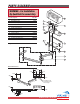
PARTS PARTS DIAGRAM DIAGRAM WARNING - For Installation By Qualified Personnel Only. Item 1 2 3 4 5 6 7 8 9 10 11 12 Description Cover, Plastic Motor/Gear Unit Chassis, Motor/Gear Strain Relief Arm Assembly, Articulated Holder, Limit Switch Limit Switch (2) Cam, Limit Switch Terminal Block Key Release Thumb Screw Positive Stop Extension Part No. VAX9PC VAX9 VAX9CH VAX9ST VAX9AA 1 6 7 9 8 10 VAX9LS VAX9LCS VAX9TB VAX9KR VAX9TS VAX9PSE 2 11 (2) Weight 40 lb. 3 4 5 12 Overall Dimensions 14.724" 4.
TABLE TABLE OF OF CONTENTS CONTENTS Parts Diagram/Parts List . . . . . . . . . . . . . . . . . . . . . . . . . . . . . . . . . . . . . . . . . . .i Important Safety Information Important Safety Instructions . . . . . . . . . . . . . . . . . . . . . . . . . . . . . . . . . . . . . .2 Important Installation Instructions . . . . . . . . . . . . . . . . . . . . . . . . . . . . . . . . .2-3 Maintenance/General Safety Precautions . . . . . . . . . . . . . . . . . . . . . . . . . . . . . .4 Terminology . . . . . .
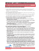
IMPORTANT IMPORTANT SAFETY SAFETY INFORMATION INFORMATION WARNING - Not following these instructions may cause severe injury or death to persons. IMPORTANT SAFETY INSTRUCTIONS WARNING – To reduce the risk of severe injury or death: 1. READ AND FOLLOW ALL INSTRUCTIONS. 2. Never let children operate or play with gate controls. Keep the remote control away from children. 3. Always keep people and objects away from the gate. NO ONE SHOULD CROSS THE PATH OF THE MOVING GATE. 4. Test the gate operator monthly.
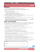
IMPORTANT IMPORTANT SAFETY SAFETY INFORMATION INFORMATION WARNING - Not following these instructions may cause severe injury or death to persons. IMPORTANT INSTALLATION INSTRUCTIONS Continued 6. Controls intended for user activation must be located at least six feet (6’) away from any moving part of the gate and where the user is prevented from reaching over, under, around or through the gate to operate the controls.
IMPORTANT IMPORTANT SAFETY SAFETY INFORMATION INFORMATION WARNING - Not following these instructions may cause severe injury or death to persons. MAINTENANCE Remove the Power Harness from the Control Board (refer to page 17) • Clean and lubricate the turning pins and gate hinges using the recommended lubricant. • Check that all mounting hardware of the gate operator is properly tighten. • Ensure that the gate moves freely. • Check for corroded parts and replace if necessary.
TERMINOLOGY TERMINOLOGY UL325 Gate Operator Classification GLOSSARY RESIDENTIAL VEHICULAR GATE OPERATOR CLASS I – A vehicular gate operator (or system) intended for use in a home of one-to four single family dwelling, or a garage or parking area associated therewith.
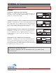
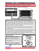
Obstruction Charger Radio Rec. Loop UL Sens Sensor Safety Loop Center Loop Center SAFETY Safety UL Radio IMPORTANT IMPORTANT SAFETY INFORMATION INFORMATION Sensor Obstruction ay Loop Sensor Rec. Power WARNING - Not following these instructions may cause severe injury or death to persons. Low Battery NOTE when Sensor the photo-beam MAX- This type of installation DOES NOT reverse the gate all the way back to its limits Motor is obstructed.
min. Motor Sensor MAX Mag. Lock Mag. LOCK Lock MAG. WARNING - Not following these instructions may cause severe injury or death to persons. Off 1 COM N.O. 3-Sided Edge Sensor 3-Sided Edge Sensor +28v Gnd Gnd +28v Radio Station Gnd UL Gnd Gnd Safety Loop Connector Connector Reopen Gnd Exit Gnd Strike Gnd Fire Open Commands Gnd N.C. Edge Sensor (contact sensor) Installation Center 60 30 Open Open Mag.
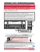
IMPORTANT IMPORTANT SAFETY SAFETY INFORMATION INFORMATION WARNING - Not following these instructions may cause severe injury or death to persons. Audible Alarm Reset Switch Installation Manual Reset for the Audible Alarm UL325 standard requires an audible alarm to go off after two consecutive events detected by the primary entrapment protection of the gate operator (obstruction sensor). The audible alarm will continue to sound for 5 minutes or until a stop command gets actuated. 0 3 2.
IMPORTANT IMPORTANT INSTALLATION INSTALLATION INFORMATION INFORMATION CAUTION - FOR USE WITH GATES OF A MAXIMUM OF 14 FT IN LENGTH AND 600 LBS. IN WEIGHT. WARNING - TO REDUCE THE RISK OF SEVERE INJURY OR DEATH TO PERSONS: This is NOT a pedestrian gate operator Do NOT Install the gate operator to lift gates 14'-0" OPEN STOP CLOSE Control Buttons 14’ maximum gate length Locate Control Buttons: 1. Within sight of the gate, 600 lb. MAX. 600 pounds maximum gate weight 2.
PLAN PLAN OF OF INSTALLATION INSTALLATION -- OPEN OPEN INSIDE INSIDE The gate must be installed in a location so that enough clearance is supplied between the gate and adjacent structures when opening and closing to reduce the risk of entrapment. Swinging gates shall not open into public access areas. C: 23-1/2" Outside Gate in Closed Position G: 4.33" Ref. H: 2.55" Ref. A: 15-3/4" Max. 90° Opening F: 15-1/2" Min. Inside Figure A – 90° Opening 7-1/4" Max.
PLAN PLAN OF OF INSTALLATION INSTALLATION –– OPEN OPEN OUTSIDE OUTSIDE The gate must be installed in a location so that enough clearance is supplied between the gate and adjacent structures when opening and closing to reduce the risk of entrapment. Swinging gates shall not open into public access areas. Outside Gate in Open Position 90° C: 19-1/2" Gate in Closed Position A: 11-3/4" Max. G: 4.33" Ref. H: 2.55" Ref.
GATE GATE OPERATOR OPERATOR INSTALLATION INSTALLATION CAUTION - If mounting bar is not welded to a frame member that runs the full length of the gate, the gate operator may damage the gate. Do not weld the bar or backing plate to a few pickets. STEP 1 14.173" Check the integrity of the gate structure and sufficiently sturdy such as pivot points are properly lubricated and surfaces are free of rust. 5.90" 5.90" 1.181" 3.937" a) Remove the Motor/Gear Assembly from its package.
GATE GATE OPERATOR OPERATOR INSTALLATION INSTALLATION STEP 4 Remount the geared motor on the chassis accordingly. STEP 5 Attach the Articulated Arms with the Positive Stop Extension to the Pivot Bracket and the Motor/Gear Assembly. NOTE - Additional holes are provided in the Pivot Bracket to assist with proper installation STEP 6 With the cover off, perform the Manual Release procedure as shown at the bottom of page 7. The gate can now be moved manually. Ensure that the gate and gate operator move freely.
GATE GATE OPERATOR OPERATOR INSTALLATION INSTALLATION Limit Switch Setup STEP 8 Additional Cam Mounting Holes A. Loosen the screws on the limit switch cams and position the cams to the desired locations. There are additional holes provided in case of a wide or tight angle of opening or closing. B. Move the gate manually and ensure that the limit switch gets actuated at the desired open and closed position. The limit switch will click when engaged by the limit cam.
GATE GATE OPERATOR OPERATOR INSTALLATION INSTALLATION Opening/Closing Setup: To have the gate operator slow down prior to reaching its limits use the following steps: 1. Setup the limit switches manually at the desired open and close position. 2. Allow the gate operator to run a full open and close cycle (from limit to limit) without interruption. Note: During the first full open and close cycle: The gate operator doesn’t slow down prior to reaching its limits.
CONTROL CONTROL BOX BOX INSTALLATION INSTALLATION WARNING - If the control box is not mounted properly it may fall, causing damage and/or injury. The control box weight is approximately 40 lbs. Be sure that the substrate being mounted to and the fasteners being used are appropriate to support the weight of the control box. 1. Remove the control board mounting plate. The plate is held in the box by four screws. 15" Standard 17" Industrial 2.
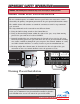
ELECTRICAL ELECTRICAL INSTALLATION INSTALLATION Caution – Do not connect the power harness to the board until the installation is ready for verification. Power Harness The X-9 Gate Operator requires a single phase AC line to operate and charge the batteries. 1. Turn off the main switch or breaker for the power line being used. 2. Move the selector switch on the Incoming Voltage Selector to the proper position (115 for 110 to 120VAC, 230 for 200 to 240VAC). 3.
ELECTRICAL ELECTRICAL INSTALLATION INSTALLATION –– SINGLE SINGLE UNIT UNIT Single Unit Connections Connect the wires from the motor unit to the terminal block mounted next to the control board. Match wire colors to the terminal block. Obstruction Overlap Delay Open Center Loop Sensor Sensor 1.5 OPEN LEFT Connect the wire harness to the “OPEN RIGHT” connector if the gate opens towards the right side. Connect the wire harness to the “OPEN LEFT” connector if the gate opens towards the left side.
ELECTRICAL ELECTRICAL INSTALLATION INSTALLATION –– MASTER/SLAVE MASTER/SLAVE Master/Slave Connections A Master/SlaveControl Board is available, when required, to run two gate operators in synchronous mode. Slave Limit Open Limit Close Slave Limit Open Limit Close Obstructionprovided insert the Delay Using Overlap the connectors Center Safety UL Radio Loop Loop Sensor Rec. wires from the motor units as shown in the diagram below.
p In si d e Ex it Lo op In si d e Re op en Lo op Ce nt er Lo op O Re ut op sid en e Lo o O ut si de VEHICULAR VEHICULAR LOOP LOOP DETECTOR DETECTOR INSTALLATION INSTALLATION Dimension A – 5’ for Single Gate Operator 6’ for Master/Slave Gate Operator A Outside Reopen Loop 5' A 5' Inside Reopen Loop Center Loop 5' Make Even with Open Gate Gate in Open Position 20 TECHNICAL SUPPORT 1 800 908 0884 Exit Loop Inside Outside 5'
VEHICULAR VEHICULAR LOOP LOOP DETECTOR DETECTOR INSTALLATION INSTALLATION WARNING – Consult the installation instructions from the loop detector manufacturer. The following statements are provided as a guide but different requirements may be required by the vehicular loop detector manufacturer. Guidelines for Vehicular Loop Detector Installation 1. Prevent sharp corners in the geometry of the loop sensor. 2. Install the appropriate number of turns for your loop geometry based on the loop perimeter.
OPEN LEFT Mag. Lock Mag. LOCK Lock MAG. UL Sens +28v Gnd UL Mag. Lock Mag. LOCK Lock MAG. Off 1 Photo Beam TECHNICAL SUPPORT 1 800 908 0884 COM N.O. +28v Gnd Radio Gnd +28v Gnd UL Gnd Reopen Gnd Center Gnd +28v Inside +28v 30 Exit N.C. Outside 22 Photo Beam COM Gnd +28v Radio Gnd +28v Gnd UL Gnd Reopen Gnd Gnd Center Off 1 Exit Edge Sensor N.C. Radio Station N.O.
ACCESSORY ACCESSORY CONNECTIONS CONNECTIONS Safety Loop UL Sensor Charger Radio Rec. UL Sens Center Loop Radio Rec. Safety Loop Center Loop on Power Radio Receiver Low Battery Motor Sensor AX When connecting the Radio Receiver carefully verify the proper connections. The maximum voltage that the control board provides for external accessories is the maximum voltage of the battery, which is about 28 volts. Mag.
M-2 ™ VIKING VIKING ELECTROMAGNETIC ELECTROMAGNETIC LOCK LOCK Standard Features • • • • • • Mounting base with electrical box Mounting Plate/Juction Box (Weld to Post) 24VDC Plug-in transformer Magnetic Lock 12VDC or 24VDC operation Mounting Screw (4) 500mA at 12VDC operation Mounting Screw Weather Cover (4) 250mA at 24VDC operation 1300 pounds of holding force Floating Plate Guide Pin (2) Use long or short pin depending on number of spacers used Flexible Washer Mounting Plate Floating Plate Magnetic Lo
OPEN RIG 24VAC Magnetic Lock Off 1 +28v Gnd COM MAX Hold Open Timer 2 N.O. N.O. N.O. OPEN STOP CLOSE COM 24 TECHNICAL SUPPORT 1 800 908 0884 25 Gnd Exit Gnd Strike Gnd Gnd Fire Open Commands Open Stop Close GND Open Stop Guard Station Center Off 1 Open 30 Hold Open Timer 60 Place the control switch box within sight of the gate, away from moving parts of the gate and out of reach of children.
SPECIAL SPECIAL FEATURES FEATURES Intelligent Obstruction Sensor (Primary Entrapment Protection) 0 Safety Loop Center Loop Sensor Obstruction Safety Loop Se MAX Hold Open Timer Turning the Trim Pot clockwise increases the sensitivity. Hold Open Open Turning the Trim Pot counterTimer clockwise decreases the sensitivity. Open 60 1. Stop the gate’s movement and reverse it momentarily. Off 1 Stop Close Center Loop Sensor min.
27 TECHNICAL SUPPORT 1 800 908 0884 27
SPECIAL SPECIAL FEATURES FEATURES Gate Overlap Setting Setting the Overlap Delay Pot to “0” will cause the master and the slave units to open and close at the same time A Master/Slave control board is required to operate two gates with a single controller. Obstruction Overlap Delay Center Loop Sensor 1.
K Mag. Lock Mag. Lock SOLAR SOLAR PANEL PANEL INSTALLATION INSTALLATION Motor Sensor Low Battery Power Charger cure 24VAC Replace the existing batteries with a battery pack of 33AHr or greater. Connect Leads from Solar Panel(s), Polarity is not important STEP 4 + – + – Red Wire Black Wire + – Connect New Batteries to Existing Leads Observing Polarity Reuse Existing Battery Fuse Holder July 14 12 10 8 5 2 *With a 40 Watt (24VDC) Panel System. NOTE – 1.
H- 4 ™ VIKING VIKING HINGE HINGE These Hinges are OPTIONAL ACCESORIES available from Viking Access Systems. Please order part number VA-HD. Standard Features • • • • Self-lubricating oil impregnated bronze bushing Port for adding a Zirk fitting 3000 lbs. capacity per pair Heat-treated stainless steel pin Set Screw (Can be removed to add lubrication) Bronze Bushing Hinge Pin (0.780" Diameter) 6.563" (Installed) 1.563" 3.187" 2.
TROUBLESHOOTING TROUBLESHOOTING Gate does not run – Motor Sensor indicator comes ON Check all motor connections to be fully engaged. Refer to page 18 and 19. Ensure that the motor connections are: a) Properly connected; b) Tight enough and; c) Match color code. Refer to page 15. Check that all motor cable connections, junctions and extensions are properly connected and color-coded. Refer to page 15.
TROUBLESHOOTING TROUBLESHOOTING Gate does not open or close Check all motor connections to be fully engaged. Refer to page 15. Check that limit switches are connected to the common and the normally close position refer to page 15. Check that the stop command is not active. Refer to page 8 and 25. Check that the UL command (photo beam and/or edge sensor) is not active. Refer to page 6, 7 and 22. Check that the vehicular loop detectors are working properly. Refer to page 20, 21 and 22.
TROUBLESHOOTING TROUBLESHOOTING Gate opens after few second delay Set the overlap delay trim pot to 0. Refer to page 28. Note: Overlap trim pot is normally recommended to use in overlapping gates. Refer to page 28. Gate opens. Closes or stops on its own Check that your external devices are working properly Check that your wires from your accessories are: a) Not shorting together b) Not shorting a power line c) Not shorting to metal or earth ground.
UL325 and UL991 listed by Underwriter Laboratories (UL). Accessible manual release via key operated mechanism. Easy solution for complex installations. Elegant design,appealing to any architectural project. Opening up to 130°. Operation speed of 10 to 13 seconds per 90°. 100% duty cycle under very wide temperature range. Very low power consumption. 800 cycles of operation on backup battery (500 lb. gate and 12’ length). Intelligent speed control with smooth start and stop, self-adjust system.