
Installation manual


30
Connecting Accessories
The Mighty Mule® 502 can accept NORMALLY OPEN, DRY-CONTACT accessories, such as; Push Button Entry
Devices and Key Pads.
Refer to the sensor manufacturer’s instructions for information about installing these devices on a vehicular gate.
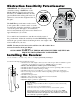
Make sure the power to the opener is turned off
before connecting Cycle Input device wiring to
the terminal blocks. Unplugging the transformer
does not turn power to the opener OFF.
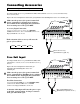
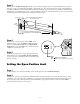
Accessory Input Connection:
Connect one of the accessory wires to the COMMON
(COM) terminal and the other to the CYCLE terminal on the
Mighty Mule® 502 control board.
Each activation of the accessory will cause the
gate to cycle as follows:
OPEN STOP CLOSE STOP
If not connecting accessories skip to next section.
Wire from Accessory
(push button, key pad, etc.)
RECEIVER
ALM
GTO RCVR.
BLK
COM
GRN
BLK
RED
CYCLE
SAFETY
EXIT
SHADOW
OPEN
EDGE
COM
CONTROL INPUTS
CLOSE
EDGE
Free Exit Input
The Mighty Mule® 500 can accept NORMALLY OPEN, DRY-
CONTACT free exit/entry devices such as GTO Wand and Loop
Detector.
Refer to the sensor manufacturer’s instructions for
information about installing these devices on a
vehicular gate.
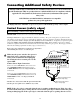
Make sure the power to the opener is turned off
before connecting Free Exit/Entry device wiring to
the terminal blocks. Unplugging the transformer
does not turn power to the opener OFF.
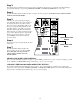
Free Exit Connection:
Connect the Exit Wand BLK wire to the COMMON (COM)
terminal and the Exit Wand BLU wire to the EXIT
terminal on the Mighty Mule® 500 control board.
Activation of this input will cause the gate to open
to the fully opened position. As long as contact is
held, gate will remain open.
Wire from Exit/Entry Device
(GTO W
and, Loop Detector etc.)
RECEIVER
ALM
GTO RCVR.
BLK
COM
GRN
BLK
RED
CYCLE
SAFETY
EXIT
SHADOW
OPEN
EDGE
COM
CONTROL INPUTS
CLOSE
EDGE