VIKING installation instructions and safety information VIKING BLUE ENABLED SOLAR EFFICIENT OPERATION class I, class II, class III, and class IV residential and commercial vehicular swing gate operator
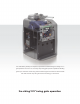
1HP with battery backup are simple but powerful words describing the Viking T-21™ gate operator. The T-21™ is our heavy duty swing gate operator capable of handling gates up to 1200 lbs. and 20’ long. Smooth efficient gate movement is achieved with soft-start and soft-stop using the newest technology in electronics.
T-21 Vehicular Gate Operator • Revision B4 • November 2009
PARTS PARTS DIAGRAM DIAGRAM Item Description 1 Output Shaft Knob 2 Output Shaft Cover 3 Clutch Key 4 Clutch and Handle 5 Output Arm 6 Output Shaft 7 Worm Gear #80 30:1 8 Sprocket 15 pitches, #50, 7/8 bore 9 Endless #50x36 Pitches 10 Sprocket 15 pitches, #50, 3/4 bore 11 24V 1 HP DC Motor/Gear Assembly 12 Spacer 13 Limit Cam & Holder 14 Limit switch (2) 15 Limit switch Holder 16 Limit Switch Bracket 17 Alarm 18 Electric Box 19 Control Board 20 Chassis 21 120V Receptacle 22 EMI Board 23 Battery Fuse Holder 24
TABLE TABLE OF OF CONTENTS CONTENTS Parts Diagram/Parts List . . . . . . . . . . . . . . . . . . . . . . . . . . . . . . . . . . . . . . . . . . .i Important Safety Information Important Safety Instructions . . . . . . . . . . . . . . . . . . . . . . . . . . . . . . . . . . . . . .2 Important Installation Instructions . . . . . . . . . . . . . . . . . . . . . . . . . . . . . . . . .2-3 Maintenance/General Safety Precautions . . . . . . . . . . . . . . . . . . . . . . . . . . . . . .
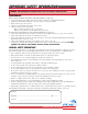
IMPORTANT IMPORTANT SAFETY SAFETY INFORMATION INFORMATION WARNING - Not following these instructions may cause severe injury or death to persons. IMPORTANT SAFETY INSTRUCTIONS WARNING – To reduce the risk of severe injury or death: 1. READ AND FOLLOW ALL INSTRUCTIONS. 2. Never let children operate or play with gate controls. Keep the remote control away from children. 3. Always keep people and objects away from the gate. NO ONE SHOULD CROSS THE PATH OF THE MOVING GATE. 4. Test the gate operator monthly.
IMPORTANT IMPORTANT SAFETY SAFETY INFORMATION INFORMATION WARNING - Not following these instructions may cause severe injury or death to persons. IMPORTANT INSTALLATION INSTRUCTIONS Continued 6. Controls intended for user activation must be located at least six feet (6’) away from any moving part of the gate and where the user is prevented from reaching over, under, around or through the gate to operate the controls.
IMPORTANT IMPORTANT SAFETY SAFETY INFORMATION INFORMATION WARNING - Not following these instructions may cause severe injury or death to persons. MAINTENANCE Remove the Power Harness from the Control Board (refer to page 15) • Clean and lubricate the turning pins and gate hinges using the recommended lubricant. • Check that all mounting hardware of the gate operator is properly tighten. • Ensure that the gate moves freely. • Check for corroded parts and replace if necessary.
IMPORTANT IMPORTANT SAFETY SAFETY INFORMATION INFORMATION CAUTION: To Reduce the Risk of Fire or Injury to Persons a) Use only the following type and size of battery(ies): Yuasa NP7-12 b) Do not dispose of the battery(ies) in fire. The cells may explode. Check with local codes for possible disposal instructions. c) Do not open or mutalate the battery(ies). Released electrolyte is corrosive and may cause damage to the eyes or skin. It may be toxic fi swallowed.
IMPORTANT IMPORTANT SAFETY SAFETY INFORMATION INFORMATION WARNING - Not following these instructions may cause severe injury or death to persons. NOTE - This type of installation DOES NOT reverse the gate all the way back to its limits when the photo-beam is obstructed. This installation is only to protect against entrapment and to comply with UL325. Photo Beam (non-contact sensor) Installation Secondary Entrapment Protection Photo beams or like must be installed to reduce the risk of entrapment.
IMPORTANT IMPORTANT SAFETY SAFETY INFORMATION INFORMATION WARNING - Not following these instructions may cause severe injury or death to persons. Edge Sensor (contact sensor) Installation Secondary Entrapment Protection UL Siren Siren GND Close Stop Open Master/Slave GND Close Guard Station Open Commands Guard Station UL Siren Master/Slave 60 Close Close Stop Open Limit Close Brake Stop Stop Radio Station Mag. Lock Hold Open Timer Hold Open Timer Open Open Mag.
IMPORTANT IMPORTANT SAFETY SAFETY INFORMATION INFORMATION WARNING - Not following these instructions may cause severe injury or death to persons. Audible Alarm Reset Switch Installation Manual Reset for the Audible Alarm UL325 standard requires an audible alarm to go off after two consecutive events detected by the primary entrapment protection of the gate operator (obstruction sensor). The audible alarm will continue to sound for 5 minutes or until a stop command gets actuated.
IMPORTANT IMPORTANT INSTALLATION INSTALLATION INFORMATION INFORMATION CAUTION - FOR USE WITH GATES OF A MAXIMUM OF 12 FT IN LENGTH AND 2000 LBS. IN WEIGHT OR 20 FT IN LENGTH AND 1200 LBS. IN WEIGHT. WARNING - TO REDUCE THE RISK OF SEVERE INJURY OR DEATH TO PERSONS: This is NOT a pedestrian gate operator Do NOT Install the gate operator to lift gates 12'-0" OPEN STOP CLOSE 2000 lb. Control Buttons MAX. 20'-0" Locate Control Buttons: 1200 lb. 1. Within sight of the gate, MAX. 2.
PLANS PLANS OF OF INSTALLATION INSTALLATION The gate must be installed in a location so that enough clearance is supplied between the gate and adjacent structures when opening and closing to reduce the risk of entrapment. Swinging gates shall not open into public access areas. Gate in Closed Position C B C = A + 12" Outside A E= (L x E 0.6) D= L L= 87 with " Maxim Viki ng A um rm (L x D 0.
PLAN PLAN OF OF INSTALLATION INSTALLATION –– DETAILS DETAILS Concrete Pad 10" 3-1/4" 2-7/16" 2.5" Recommended Area for Conduit(s) 23-1/4" 11" 7-5/8" Center of Output Shaft Operator Cover Operator Chassis Gate Operator Concrete Pad 20" 6" Minimum Drill for a 1/2" x 3-1/2" Red Head Anchor (4) Places 2.5" 12" Conduit Location 30" Grade Level See Note 2 Gate Operator Concrete Pad 1. Follow the local building code to determine the required depth of the concrete pad. 2.
GATE GATE OPERATOR OPERATOR INSTALLATION INSTALLATION CAUTION - If mounting bar is not welded to a frame member that runs the full length of the gate, the gate operator may damage the gate. Do not weld the bar or backing plate to a few pickets. STEP 1 Release the clutch (see page 7). Cut the extension arms according to the desired plan of installation (Figure A on page 10). Note: Leave some additional material when cutting the extension arms to allow for additional adjustment.
GATE GATE OPERATOR OPERATOR INSTALLATION INSTALLATION Step 4 Upon observation of the satisfactory arrangement of the articulated arm and bracket, weld all pieces securely. Paint the arm to protect it from rusting. STEP 5 Upon test of the installation, loosen the clutch and rotate it until it lines up with the notches in the Output Shaft. Insert the Clutch Key. Insert Clutch Key STEP 6 Check the Clutch adjustment. The Clutch is shipped factory adjusted.
OPEN RIGHT OPEN LEFT ELECTRICAL ELECTRICAL INSTALLATION INSTALLATION Caution – Do not connect the power harness to the board until the installation is ready for verification. Red 24VAC Green White Auxiliary Power Connection. See page 27 for further details. Power Harness Earth Ground 115V/220V Power Switch 3A FUSE Part # VAEMI Power Ground To Transformer Neutral Hot Fail Safe/Secure 24V BAT Black The Gate Operator requires a single phase AC line to operate and charge the batteries. 1.
Motor Sensor ELECTRICAL ELECTRICAL INSTALLATION INSTALLATION –– SINGLE SINGLE UNIT UNIT Low Battery UL Sensor Power Radio Rec. Charger OPEN LEFT OPEN RIGHT Connect the wire harness to the “OPEN RIGHT” connector if the gate opens to the right. Connect the wire harness to the “OPEN LEFT” connector if the gate opens to the left. afety Loop Power Connections Motor Sensor OPEN RIGHT Low Battery UL Sensor Radio Rec.
LIMIT LIMIT SWITCH SWITCH SET-UP SET-UP Limit Switch Setup Cam Wheel Clutch Guide Pin Limit Switch Cam STEP 7 A. Loosen the screws on the Limit Switch Cams. B. With the operator cover still off, remount the articulated arm, making sure the cam wheel pin is engaged with the clutch. C. Move the gate manually to the closed position. D. Move the Limit Switch Cams on the Cam Wheel to actuate each limit switch.
LIMIT LIMIT SWITCH SWITCH SET-UP SET-UP Opening/Closing Setup 1. Setup the limit switches manually at the desired open and close position. 2. Allow the gate operator to run a full open and close cycle (from limit to limit) without interruption. Note: During the first full open and close cycle: The gate operator doesn’t slow down prior to reaching its limits. During subsequent cycles: The gate operator will slow down prior to reaching its limits. 3.
24 + 28 v + n io G nd St G nd Ra o di o di Ra 28 + C . .C N G .L O C v G nd K U L or ct ne on C nd G pen Reo op Lo nd G er rg ha er ery C w att tor Po B o w M Lo ck he C M L o ag ck . 24V BAT M O . .O N v at 28 M A OPTIONAL OPTIONAL VIKING VIKING BLUE BLUE INSTALLATION INSTALLATION Fail Safe/Secure C nd . in m ds an m m o C n pe O n io at St 36 C 35 C 3 JP Mag. Lock Mag. LOCK Lock MAG. COM 41- RN 9J D: T CI FC ial # r e S N.O.
ELECTRICAL ELECTRICAL INSTALLATION INSTALLATION –– MASTER/SLAVE MASTER/SLAVE Master/Slave Connections Outside Interconnecting Conduit Inside Master Unit Slave Unit Caution – Do not run Master/Slave communication cable in the same conduit as the power supply (120-220V) cable.
O ut si de VEHICULAR VEHICULAR LOOP LOOP DETECTOR DETECTOR INSTALLATION INSTALLATION e op tsiden Lo u O op Re op r Lo e t n Ce oop id Ins e nL ope e R Loo p In si de t Exi Note: Not all loops may be necessary for every installation.
VEHICULAR VEHICULAR LOOP LOOP DETECTOR DETECTOR INSTALLATION INSTALLATION WARNING – Consult the installation instructions from the loop detector manufacturer. The following statements are provided as a guide but different requirements may be required by the vehicular loop detector manufacturer. Guidelines for Vehicular Loop Detector Installation 1. Prevent sharp corners in the geometry of the loop sensor. 2. Install the appropriate number of turns for your loop geometry based on the loop perimeter.
LOOP LOOP RACK RACK INSTALLATION INSTALLATION Looprack – Viking Part # VA LR Looprack Wiring Harness – Viking Part # VA LRH Outside Twist Wire Outside the Loop 6 Twists/Foot Until Its Connection to the Loop Rack Viking Loop Rack Exit Center Outside Safety Loop Reopen Exit OP 28V Gnd Exit Center Reopen Center Loop CN Center RO Reopen Inside Safety Loop Exit Loop Control Board Connector Inside Loop Connector UL iren Siren GND Close Stop Open Master/Slave GND Close Stop Guard Station
OPTIONAL OPTIONAL ACCESSORY ACCESSORY CONNECTIONS CONNECTIONS Safety Connections 1 Safety Loop Detector Photo Beam 2 Edge Sensor Center Loop Detector 1 op Open Open 3 3 Overlap Delay min. 1.5 1.5 Radio Station Mag.
OPTIONAL OPTIONAL ACCESSORY ACCESSORY CONNECTIONS CONNECTIONS Radio Receiver When connecting the Radio Receiver carefully verify the proper connections. The maximum voltage that the control board provides for external accessories is the maximum voltage of the battery, which is about 28 volts. In the event of an electrical short in the power to the accessories, the board will protect itself by shutting down and will remain shut down until the short is corrected.
M-2 ™ OPTIONAL OPTIONAL ELECTROMAGNETIC ELECTROMAGNETIC LOCK LOCK Standard Features Mounting base with electrical box Mounting Plate/Juction Box (Weld to Post) 24VDC Plug-in transformer Magnetic Lock 12VDC or 24VDC operation Mounting Screw (4) 500mA at 12VDC operation Mounting Screw Weather Cover (4) 250mA at 24VDC operation 1300 pounds of holding force Floating Plate • • • • • • Guide Pin (2) Use long or short pin depending on number of spacers used Flexible Washer Mounting Plate Floating Plate Mag
OPTIONAL OPTIONAL ACCESSORY ACCESSORY CONNECTIONS CONNECTIONS Magnetic Lock 1 External supply for the magnetic lock must be provided. This will prevent rapid drainage of the battery in the event of power failure. 2 Relay Contact 10A-250VAC nnector Radio Station N.O. Connection Locations Gnd Mag. Lock 1 UL Gnd +28v Gnd Radio +28v Gnd +28v Loop Co Radio Station COM N.C. Mag. Lock Viking Access Systems can supply an excellent Magnetic Lock unit (part number VA-MAG13).
SPECIAL SPECIAL FEATURES FEATURES Auto-Open Feature 0 Radio Rec. Reopen Loop UL Sens N.O. 27 Gnd +28v Ra Gnd UL Gnd Reopen Gnd Center Gnd Safety Loop Connector Connector N.C. +28v Radio Rec. Off 1 Exit Gnd Strike Gnd Fire Gnd Open Open Commands COM Gnd +28v Radio Gnd +28v Stop Close Guard Station GND Open Stop Close GND Siren Mag. Lock Mag. LOCK Lock MAG.
Stop Open Limit Li Hold Open Timer Mag. Lock Intelligent Obstruction Sensor (Primary Entrapment Protection) min. min. 3 1.5 Overlap Delay Overlap Delay Overlap Delay Mo MAX Lo Obstruction Sensor 0 1.5 Sensor Obstruction Center Loop Center Loop Sensor Safety Loop Safety Loop Center Loop UL Sensor Po Radio Rec. Ch arger UL Sensor Safety Loop Radio Rec. UL Sens Radio Rec.
SPECIAL SPECIAL FEATURES FEATURES Fail Safe/Fail Secure Operation The gate operator contains a unique design that allows the user to move the gate manually in case of power failure. Fail Safe: If the operator has been installed with an Elbow Arm, the Clutch Key can be removed and the gate can me moved manually with a relative low amount of force. Remove Clutch Key Fail Secure: This unit is shipped with the default fail secure feature.
n e Guard Station Open Commands off 1sec Safety Connector Radio Stati Gate Overlap Setting 60sec Hold Open Timer Open Setting the Overlap Delay Pot to “0” will cause the master and the slaveStop units to Close 30sec open and close at the same time Hold Open Timer Limit Limit Close Stop Open Hold Open Timer 1.5 Overlap Delay min. Overlap Delay Mag. Lock Mo MAX Lo Center Loop Sensor Obstruction Safety Loop UL Sensor Po Radio Rec.
BATTERY BATTERY && EMI EMI BOARD BOARD LOCATION LOCATION The Batteries are Located Behind the Panel Door The EMI Board is Located Behind the Panel Door TECHNICAL SUPPORT 1 800 908 0884 31
Safety Loop Connector Connector Radio Station N.O. COM N.C. Mag. Lock Mag. Lock Connect the Solar Panel Controller as shown. Check Motor Motor Sensor Low Battery Power Charger – + – Remove existing batteries. Use new external batteries of 35 AHr or greater and connect them in series to provide a 24V system. 32 TECHNICAL SUPPORT 1 800 908 0884 24VAC + Fail Safe/Secure 24V BAT Remove the existing Power Harness and use the power harness provided. Radio Rec.
ctor ctor Radio Station Mag. LOCK Lock MAG. N.O. COM N.C. Mag. Lock OPTIONAL OPTIONALSOLAR SOLAR PANEL PANEL INSTALLATION INSTALLATION Mag.
L G nd Ex it St rik e ds an m om C nd G O nd G n pe O Fi re 60 30 O pe n D n io at St rd ua G N X A G M e lo s e av Sl r/ ts e a M lo C se 36 C 3 C 35 n ak e m . in Radio Rec. JP Power Mag. LOCK Lock MAG. Mag. Lock N.C. COM N.O. +28v Gnd +28v Radio Radio Station If you are using the computer: • Hold the computer near the Gate Operator. • Run the application by clicking the icon on the desktop. • Select “Setting” in the top right of the screen.
TROUBLESHOOTING TROUBLESHOOTING Gate does not run – Motor Sensor indicator comes ON Check all motor connections to be fully engaged. Refer to page 15. Check the 15 Amp fuse in the control board. Check that the reset switch is set in the “Reset’ position. Gate does not run – Motor Sensor indicator is OFF Check all motor connections to be fully engaged. Refer to 15. Check that limit switches are connected to the common and the normally close position refer to page 17.
TROUBLESHOOTING TROUBLESHOOTING Gate does not open or close Check all motor connections to be fully engaged. Refer to page 15. Check that limit switches are connected to the common and the normally close position. Refer to page 17. Check that the stop command is not active. Refer to page 8 and 26. Check that the UL command (photo beam and/or edge sensor) is not active. Refer to page 6, 7 and 23. Check that the vehicular loop detectors are working properly. Refer to page 20, 21 and 23.
TROUBLESHOOTING TROUBLESHOOTING Gate opens after few second delay Set the overlap delay trim pot to 0. Refer to page 30. Note: Overlap trim pot is normally recommended to use in overlapping gates. Refer to page 30. Gate opens. Closes or stops on its own Ensure that the key for manual release is in the lock position. Refer to page 7. Make sure that the ‘Charger’ LED is on, indicating that there is AC power.
Notes
our continuous commitment to excellence Viking Access Systems is continuously working hard to identify and design products that will appeal to the industry and it’s needs. As technology continues to advance, we have developed a completely efficient and intelligent line of gate operators to meet the changing demands. These machines offer; full UL325 and UL991 compliance, soft-start and soft-stop, intelligent obstruction sensors, continuous operation (100% duty cycle) and extreme power efficiency.
VIKING standard features and operator specifications Accessible manual releases • Fail-Safe option sets the gate to automatically transfer to a fail-safe mode in the event of a power failure, allowing the gate to be pushed open without the use of special knowledge of the equipment • Fail-Secure option sets the gate to mechanically lock in the event of a power failure, allowing no manual movement without the use of the manual release • Standard Auto Open feature • Elegant design, appealing to any architect