INSTALLATION INSTRUCTIONS AND SAFETY INFORMATION F O R T H E V I K I N G Q -7 G AT E O P E R ATO R CLASS II, CLASS III, AND CLASS IV Heavy-Duty Commercial Vehicular Slide Gate Operator
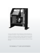
The Q-7™ gate operator has the capacity to operate slide gates up to 7000 lbs. and 120 ft. in length at 100% duty cycle under extreme conditions. This efficient operator provides a solution for high traffic commercial and industrial slide gate applications. The Viking Q-7™ gate operator offers efficiency and technology combined in a single package.
Q-7 Vehicular Gate Operator • Revision Q7NXMN10.
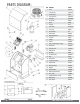
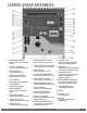
PARTS DIAGRAM: Item Description 2 Part No.
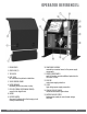
OPERATOR REFERENCES: 1. FRONT COVER 10. POWER BOX ASSEMBLY removable; convenient access to the power supply 2. COVER LOCK (2) components 3. TOP COVER 11. MOTOR POWER SWITCH & breaker; provides additional protection for 4. LOOP RACK switch the motor circuitry . for convenient loop detector installation 12. EMI FUSE 5. VFLEX CONTROL BOARD main power supply protection 6. MOTOR BREAKER 13.
CONTROL BOARD REFERENCES: 1. POWER HARNESS CONNECTOR provides power to the control board. pg 18-19 2. “OPEN LEFT” & “OPEN RIGHT” provides power to the motor. pg 20 3. LIMIT SETUP BUTTONS sets limit positions. pg 20-21 4. FEATURE ACTIVATION TRIM POTS activate and set features. pg 24 5. “EPS1” CONNECTOR monitors manual release operation. 6. “EPS2” CONNECTOR monitors the limit positions. 7. EMI BOARD CONNECTOR monitors the high voltage power supply. 8.
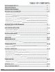
TABLE OF CONTENTS: PARTS DIAGRAM/PARTS LIST OPERATOR REFERENCES CONTROL BOARD REFERENCES IMPORTANT SAFETY INFORMATION Important Safety Instructions Important Installation Instructions Maintenance General Safety Precautions Operator Classification Photo Beam (non-contact sensor) Installation Edge Sensor (contact sensor) Installation Manual Release Audible Alarm Reset Installation Warning Placard Installation IMPORTANT INSTALLATION INFORMATION Specifications 2 3 4 6-12 6 7 8 8-9 9 10 11 11 12 12 13 13 GAT
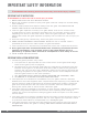
IMPORTANT SAFETY INFORMATION ! WARNING! Not Following these instructions may cause severe injury or death. IMPORTANT SAFETY INSTRUCTIONS ! WARNING! To reduce the risk of severe injury or death. 1. READ AND FOLLOW ALL INSTRUCTIONS . 2. Never let children operate or play with gate controls. Keep the remote away from children. 3. Always keep people and objects away from the gate. NO ONE SHOULD CROSS THE PATH OF THE MOVING GATE. 4. Test the gate operator monthly.
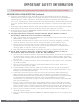
IMPORTANT SAFETY INFORMATION ! WARNING! Not Following these instructions may cause severe injury or death. IMPORTANT INSTALLATION INSTRUCTIONS (Continued) 6. Controls intended for user activation must be located at least six feet (6’) away from any moving part of the gate and where the user is prevented from reaching over, under, around or through the gate to operate the controls. Exception: Emergency access controls only accessible by authorized personnel (i.g.
IMPORTANT SAFETY INFORMATION ! WARNING! Not Following these instructions may cause severe injury or death. MAINTENANCE Remove the Power Harness from the Control Board. (refer to page 18) • Clean and lubricate the gate track wheels using the recommended lubricant. • Inspect the track for any signs of cracking or separation. • Check that all mounting hardware of the gate operator is properly tighten. • Ensure that the gate moves freely. • Check for corroded parts and replace if necessary.
IMPORTANT SAFETY INFORMATION ! CAUTION: To Reduce the Risk of Fire or Injury to Persons: a. Use only the following type and size battery(ies): Yuasa NP7-12 or VIKING DUBA12 b. Do not dispose of the battery(ies) in fire. The cells may explode. Check with local codes for possible disposal instructions. c. Do not open or mutilate the battery(ies). Released electrolyte is corrosive and may cause damage to the eyes or skin. It may be toxic if swallowed. d.
IMPORTANT SAFETY INFORMATION ! WARNING! Not Following these instructions may cause severe injury or death. NOTE: This type on installation does not reverse the gate all the way back to its limits when the photo beam is obstructed. This installation is only to protect against entrapment and to comply with UL325. Secondary Entrapment Protection Photo Beam (non-contact sensor) Installation • Photo beams or like must be installed to reduce the risk of entrapment.
IMPORTANT SAFETY INFORMATION ! WARNING! Not Following these instructions may cause severe injury or death. NOTE: This type on installation dOEs NOT reverse the gate all the way back to its limits when the edge sensor is obstructed. This installation is only to protect against entrapment and to comply with UL325. Secondary Entrapment Protection Edge Sensor (contact sensor) Installation • Edge Sensors or like must be installed to reduce the risk of entrapment.
IMPORTANT SAFETY INFORMATION ! WARNING! Not Following these instructions may cause severe injury or death. Audible Alarm Reset Switch Installation Manual Reset for the Audible Alarm • UL325 standard requires an audible alarm to go off after two consecutive events detected by the primary entrapment protection of the gate operator (obstruction sensor). • The audible alarm will continue to sound for 5 minutes or until a stop command gets actuated. • The Stop command can be actuated in two different forms: 1.
IMPORTANT INSTALLATION INFORMATION ! CAUTION: To Reduce the Risk of Fire or Injury to Persons: ! WARNING: For use with gates at a maximum 7000 lbs. in weight or 120 ft. in length. DO NOT allow pedestrian use of this gate DO NOT install the gate operator to lift gates Locate Control Buttons: 1. Within sight of the gate, 2. At a minimum height of 5 feet so small children are not able to reach it; and 3. At least 6 feet away from all moving parts of the gate. 7000 lb.
GATE OPERATOR INSTALLATION Concrete Pad Installation 1. Follow the local building code to determine the required depth of the concrete pad. 2. Pad measurements recommended by Viking Access Systems are at least 28” long, 18” wide and 24” deep to ensure the stable operation of the operator, and a minimum of 4” above level grade to avoid any flooding of the machinery. 3.
GATE OPERATOR INSTALLATION Positive Stop Installation ! IMPORTANT: This operator REQUIRES that a positive stop be installed at the close position. This will be used as a reference to relearn the limit positions if the gate has been operated manually while released or if the EPS2 Cable has been disconnected. NOTE: Viking Access Systems does not provide any form of positive stops.
GATE OPERATOR INSTALLATION Operator Positioning ! IMPORTANT: All openings of a horizontal slide gate are guarded or screened from the bottom of the gate to a minimum of 4 feet (1.22 m) above the ground to prevent a 2-1/2 inch (57.2 mm) diameter sphere from passing through the openings anywhere in the gate, and in that portion of the adjacent fence that the gate covers in the open position. 16 VIKING TECHNICAL SUPPORT 1.800.908.
GATE OPERATOR INSTALLATION ! TECHNICAL TIP: Before completing the installation procedure; • Open and close the gate manually, making sure there is sufficient space between the gate and adjacent walls. • Check that the wheels are turning freely on the track and there are no restrictions while pushing the gate to the open and closed positions. • Confirm that there is adequate spacing for the guide rollers and that there are no restrictions throughout the travel of the gate.
ELECTRICAL INSTALLATION High Voltage Supply Option ! Caution: Always turn off power breakers when working with high voltage. DO NOT connect the “Power Harness” to the Control Board until the electrical installation is complete and ready for verification. STEP 1 3d At the “Power Box”: a. Setet the “Voltage Selector” according to the supply voltage (115V or 230V). b. Turn the “AC Power” switch ON STEP 2 ! WARNING: SINGLE PHASE AC ONLY 3c At the “J-Box”: a.
ELECTRICAL INSTALLATION Solar Supply Option ! IMPORTANT: The number of cycles achieved daily is dependent on many factors, including local solar radiation data and power consumption of the motor and accessories. It is very important that you consider this when using solar power. ! Tip: Solar efficency can be increased by activating the “Pre-Warning” A feature. The “Aux.
LIMITS SETUP ! IMPORTANT: 1. Before the initial limits setup, a Positive Stop MUST be installed at the close position. This will be used as a reference to relearn the limit positions if the gate has been operated manually while released or if the EPS2 Cable has been disconnected. 2. In the event of a complete power failure, including battery backup, the limit positions may have may been cleared and will need to be reset as described. STEP 1 Connect the “Motor Harness” to the Control Board. 1a 1b a.
LIMITS SETUP ! IMPORTANT: If the gate has been manually released and re-engaged: 1. The Open Limit LED will be illuminated solid and the Close Limit LED will be flashing. 2. The gate will not run in the open direction until step 4 is repeated on page 20. Open Limit Close Limit To Readjust the Close Limit: To Readjust the Open Limit: 1. 1. Clear the current limit setting by holding down the “Close Limit” button until the LED is flashing. 2. Repeat STEP 2 on page 20 to set the limit. 3.
MASTER/SLAVE SETUP Two Wire Communication ! IMPORTANT: DO NOT run the Master/Slave communication cable in the same conduit or within 12” of 115 - 230v power supply cables. ! Technical Tip: DO NOT set the “Timer” and/or “Overlap” features on both operators Control Boards. Only turn these features on at the Master Control Board.
MASTER/SLAVE SETUP Wireless Communication Options ! Technical Tip: DO NOT set the “Timer” and/or “Overlap” features on both operators Control Boards. Only turn these features on at the Master Control Board. REQUIRED ADD-ON: 1. Choose option A or B A. Viking Konnect - Wireless Master/Slave Kit PART# VA-KONNECT-MS B. Viking Blue - Wireless Master/Slave Kit PART# VA-BLUE-MSKT 2. Antenna Extension Cables (2) PART# VA-RPSMA Connect the Modules provided to the “V.
CONTROL BOARD SETUP Initial Settings “Speed” Motor Speed “ODS” Obstruction Detection Sensor Increases or decreases the speed of gate travel. Sets the amount of force required to trip the inherent obstruction sensor. See page 26 for more details about this feature. “Overlap” Overlap Delay Delays the gate from opening for the selected amount of time from 1-6 seconds. ! Typically not used on slide gates.
CONTROL BOARD SETUP Initial Settings NOTE: Installing a shunt or jumper on the pins will activate the feature. “Auto Open” - Power Failure Option Opens the gate automatically during power failure. Resumes normal operation when power is restored. “Last Open” - Power Failure Option Opens the gate automatically when the battery backup voltage is critically low. “Pre-Warning” Initiates two options for an audio or visual warning 3 seconds prior to gate motion and will continue: 1.
CONTROL BOARD SETUP Obstruction Sensor (Primary Entrapment Protection) ! IMPORTANT: The appropriate “ODS” setting is dependant upon the gate installation and construction. Set this feature accordingly. Additional Safety equipment should be used to reduce possible risk of injury or vehicle damage. “ODS” Obstruction Detection Sensor The Obstruction Sensor detects obstructions in the path of the traveling gate.
CONTROL BOARD SETUP Viking Heater The operator has an integrated heater that is thermostatically controlled. Activate this feature when the operator is used in application temperatures down to -20°F (-29°C). To set the heater to turn on at the Close Limit: 1. Use the “Diagnose” button to scroll through the LCD Display to “HEATER CLS” 2. Press and hold the “Stop” button on the control board. 3. Press and release the “Diagnose” button to turn this feature ON and OFF.
(THIS PAGE LEFT BLANK INTENTIONALLY) 28 VIKING TECHNICAL SUPPORT 1.800.908.
ACCESSORY CONNECTIONS Re-Open Photo Beam (vehicular Safety) NOTE: This type of photo-beam installation will stop then RE-OPEN the gate all the way to the open limit, when the beam is obstructed. Intended for vehicular safety ONLY. For the purpose of pedestrian entrapment, see pages 10-11. N.O. COM (-) (+) Note regarding Photo Beam types: Check for proper operation: Fail-Safe type - connect the “N.C.” terminal of the photo beam to the “Re-Open” terminal on the control board.
ACCESSORY CONNECTIONS Radio Receiver (Typical) ! IMPORTANT: The Hold Open “Timer” setting (page 24) affects how the gate will respond to the radio receiver command. The control board provides two modes of operation that a radio receiver can control the gate: Open-Stop-Close 1. By having the radio receiver connected as illustrated and with the Hold Open Timer OFF (see page 24): COM N.O. (-) (+) Every command of the radio transmitter will control the gate as follows: a. First command opens the gate, b.
ACCESSORY CONNECTIONS Anti-Tailgate, Open Commands & Guard Station ! TECHNICAL TIP: For more information regarding accessory connections and terminal functions, refer to “Appendix (A)” on pages 42-43. Open Commands “Exit ”, “Fire” and “Strike” input terminals all provide an open command to the control board. Any device connected as shown will open the gate. + + - + - N.O. COM N.O. COM N.O. COM Guard Station ! All three buttons must be a Normally Open “N.O.
ACCESSORY CONNECTIONS Viking Loop Rack TIP: This operator may be equipped with a pre-wired Loop Rack that plug-in type loop detectors can be connected to. This provides a convenient alternative to the box type loop detectors that would need to be wired to the control board. Viking does not provide either type of loop detectors. 32 Loop Rack: Part # VA-LR Loop Rack Wiring Harness: Part # VA-LRH VIKING TECHNICAL SUPPORT 1.800.908.
ACCESSORY CONNECTIONS Guidelines for Loop Installation 1. Prevent sharp corners in the geometry of the loop sensor. 2. Install the appropriate number of turns for your loop geometry based on the loop perimeter. Use Table C (below) as a guide. 3. Use XLP (cross-linked-polyethylene) type of wire. This wire reduces the effects of moisture and other environmental events in altering the functionality of the vehicular loop detector. 4. Twist the lead wire at least 6 turns per foot. 5.
ACCESSORY CONNECTIONS Magnetic Lock, Lock Solenoid NOTE: Viking Access Systems does not provide external gate lock devices. These items can be purchased from your dealer or distributor. Power for the Locks: Magnetic Lock Do not use the 24VDC power supplied by the control board. An external power supply, or plug-in transformer, must be used for the magnetic lock or lock solenoid. Plug the transformer into the “120VAC” receptacle provided at the operators Power Box.
SYNCHRONIZATION WITH B-12 Barrier Arm (B-12) Synchronization Option NOTE: The Control Board provides a convenient solution for applications that require synchronized operation with the Viking Barrier Arm Operator model B-12. This type of application opens and closes in the following pattern: 1. Open Command is provided only to the Viking B-12 Barrier Arm Operator. 2. The Barrier Arm will delay to open until this Gate Operator reaches its Open Limit. 3.
TROUBLESHOOTING LED References In addition to the LCD Display, the control board LEDs monitor the various circuits of the control board. Use the table below to identify the corresponding “TS Ref#” and refer to page 38-41 for further troubleshooting. Page 41 TS Ref#(s) # LED Status Meaning 1 OFF At Closed Limit and Magnetic Lock Relay state is closed across “COM” & “N.C.”. (pg 34). Gate should be at the Close Limit. SOLID Not at Closed Limit and Magnetic Lock Relay state is closed across “COM” & “N.
TROUBLESHOOTING LED References Use the table below to identify the corresponding “TS Ref#” and refer to page 38-41 for further troubleshooting. Pg 41 # LED Status Meaning 9 OFF Normal Condition. SOLID Control Board is receiving an input from a device connected to the C Loop terminal (pgs 32, 42). OFF Normal Condition. SOLID Control board is receiving an input for a device connected to any of the following input terminals: Exit, Fire, Strike or Open (pgs 31, 42). OFF Normal Condition.
TROUBLESHOOTING LCD Display References The control board is equipped with a LCD Display that provides operator information, current conditions, settings, diagnostics and error messages. Use the table below to identify the corresponding “TS Ref#” and refer to page 41 for further troubleshooting. 1. Error Messages will be displayed first. Call out LCD Display, Diagnose Button and Diagnose LED 2. The ”Diagnose” LED will flash consecutively indicating how many Error Messages are available. 3.
TROUBLESHOOTING LCD Display References Page 41 TS Ref #s LCD MSG Meaning SEARCH POS STOP Needs to search for the Positive Stop, that has been installed at the close position, in order to use as a reference for the limits after manual operation. Multi Meter Displays MOT AMP __._ A MOT VOLT __._ VDC AC VOLT __._ VAC CHARGE __._ VDC BAT VOLT __.
TROUBLESHOOTING LCD Display References Page 41 TS Ref #s LCD MSG Meaning Error Messages ERR AC LOW ERR AC HIGH ERR AC NO AC ERR CHRG HIGH ERR CHRG CHECK 4A ERR BAT LOW Indicates that the 24VAC supply to the VFlex Board is too low from the 115/230 power supply. 1, 3. 20 Indicates that the 24VAC supply to the VFlex Board is too high from the 115/230 power supply. 1, 3, 20 Indicates that there is no 24VAC supply detected to the VFlex Board from the 115/230 power supply.
TROUBLESHOOTING Solutions Begin the troubleshooting process by referring to the error messages on the LCD Display and/or the Status LEDs on the control board. Use pages 36-40 to identify the Troubleshooting Reference # (TS Ref#) then reference the table below. TS Ref# CHECK 1 Page Ref# Check that the high voltage power supplied to “J-Box” is within range. 100v-120v or 200v-240v. pg. 18 2 Remove and check EMI Fuse for continuity. pg.
Appendix (A) Access Control Connections Power Connections The control board provides a 24VDC output to power external devices and controls. Alternatively, for devices that require a power supply other than 24VDC , the operators Power Box contains a convenient 120VAC receptacle to connect a plug-in transformer. Terminals Connections and Input Functions: Viking Terminal “+28v” “GND” “GND” “Radio” Function “C” “N.O.
APPENDIX (A) Relays In General NOTE: Viking Access Systems does not provide the external safety devices and access controls. These items can be purchases from your dealer or distributor. In General Glossary of Terms In regards to the Viking control board, all external safety devices and access controls contain, and are, simple relays that provide an input to the Viking control board when the device is activated. 1. Terminal: Wire Connections. 2.
Appendix (B) Common Radio Receivers - Connections 44 VIKING TECHNICAL SUPPORT 1.800.908.
APPENDIX (C) Solar Applications NOTE: Viking recommends Solar Package (part # VA-SOCHP) for most general solar applications. Alternatively, individual and third party solar components can be used. The following are minimum system requirements and installation information. Panels • Voltage 24V • Wattage 80W (minimum) Cut the wires coming from the toroidal transformer. Connect the solar panel cables to the power harness as shown.
VIKING EXPANSION PRODUCTS VIKING KONNECT Master/Slave Kit Secure and reliable Master/Slave communication using Viking’s Konnect technology. Paired with the Viking App, each module also doubles as a diagnostic tool. Part# VA-KONNECT-MS ***Q -7, B-12 & ECU Operators require (2) Antenna Extension Cables (part# VA- RPSMA)*** VIKING KONNECT Diagnostic Tool On-site remote access to the operator from the convenience of a compatible hand held device.
OUR CONTINUOUS COMMITMENT TO EXCELLENCE Viking Access Systems is continuously working hard to identify and design products that will appeal to the industry and its needs. As technology continues to advance, we have developed a completely efficient and intelligent line of gate operators to meet the changing demands. These machines offer: full UL325 and UL991 compliance, soft-start and soft-stop, intelligent obstruction sensors, continuous operation (100% duty cycle) and extreme power efficiency.
STANDARD FEATURES AND OPERATOR SPECIFICATIONS • UL Listed; UL325 and UL991 • Intelligent obstruction detection with adjustable sensitivity • ETL Listed; UL325 and UL991 • Built-in climate control for cold weather applications • Elegant design, appealing to any architectural project • Plated and powder coated steel chassis • Adjustable travel speed • Up to 120’ maximum gate opening • 100% duty cycle • 100 cycles of operation on backup battery (2000 lb.