7/19-INCH PREMIUM TFT-LCD MONITOR USER MANUAL Please read this manual thoroughly before use, and keep it handy for future reference.
………………………………………………………….…… 2~3 …………………………………………………………….......................... 4 ……………………………....................... 5 SAFETY INSTRUCTION CAUTIONS FCC RF INTERFERENCE STATEMENT CONNECTING WITH EXTERNAL EQUIPMENT …………………………………… 6 ………………………………………………………………… 7 ……………………………………………………….. 8 ~ 17 MOUNTING GUIDE …………………………………………………………………….. 18 ………………………………………… 19 ……………………………………………………………… 20 ……………………………………………………………………… 21 ………………………………………………….........
Important Safety Instruction 1. Read these instructions. 2. Keep these Instructions. 3. Heed all warnings. 4. Follow all instructions. 5. Do not use this apparatus near water. 6. Clean only with dry cloth. 7. Do not block any ventilation openings. Install in accordance with the manufacturer’s instructions. 8. Do not install near any heat sources such as radiators, heat registers,stoves, or other apparatus (including amplifiers) that produce heat. 9.
- The apparatus shall not be exposed to dripping or splashing and that no objects filled with liquids, such as vases, shall be placed no the apparatus. 14 Minimum distances(e.g. 10cm) around the apparatus for sufficient ventilation. “WARNING – To reduce the risk of fire or electric shock, do not expose the apparatus to rain or moisture.” “The apparatus shall not be exposed to dripping or splashing and no objects filled with liquids, such as vases, shall be placed on the apparatus.
CAUTION The power supply cord is used as the main disconnect device, ensure that the socket-outlet is located/installed near the equipment and is easily accessible. ATTENTIONN Le cordon d`alimentation est utillsé comme interrupteur général. La prise de courant doit être située ou installée à proximité du matériel et être facile d`accès ▶ NEVER REMOVE THE BACK COVER Removal of the back cover should be carried out only by qualified personnel.
NOTE This equipment has been tested and found to comply with the limits for a Class A digital device, pursuant to Part 15 of the FCC Rules. These limits are designed to provide reasonable protection against harmful interference in a residential installation. This equipment generates, uses and can radiate radio frequency energy and, if not installed and used in accordance with the instructions, may cause harmful interference to radio communications.
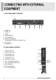
A. BOTTOM PANEL CONTROL 1 2 3 4 5 6 7 8 9 1. HDMI2 IN 2. HDMI1 IN 3. DVI IN 4. VGA(D-SUB) IN 5. PC STEREO IN 6. AUDIO OUT(Speaker) 7. COMPONENT Y,Pb,Pr & SOUND L,R IN 8. DC 12V IN 9. TRIGGER IN B. SIDE PANEL CONTROL 1 1. VIDEO1(AV1) IN 2. VIDEO1(AV1) OUT 3. VIDEO2(AV2) IN 4. VIDEO2(AV2) OUT 5. S-VIDEO(Y/C) IN 6. S-VIDEO(Y/C) OUT 7. AV1 & S-VIDEO AUDIO IN 8. AV1 & S-VIDEO AUDIO OUT 9. AV2 AUDIO IN 10. AV2 AUDIO OUT 11. DC 12V ADAPTOR 2 3 4 5 6 7 9 10 8 11 6 ……………………………………………………………………….
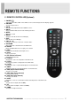
C. REMOTE CONTROLLER(Optional) 1. POWER( ) Turns the power ON or OFF. There will be a few seconds delay before the display appears. 2. SOURCE Selects an input source. 3. AUTO Auto geometry adjustment in the RGB PC source. 4. HOLD Stops the Motion Detection & Auto switching functions. 5. MUTE Mutes the sound. 6. MENU Activates and exits the On Screen Display. 7. EXIT Exits the On Screen Display. 8. VOL(◀ & ▶) Increases or decreases the level of audio volume. 9.
D. FRONT KEY CONTROL 1 / 2. ◀ VOL ▶ Adjust the volume and menu settings. 3 / 4. ▲ / ▼ These buttons allow user to enter the sub-menu of the activated function. The up(▲) button is HOLD function and stop the Trigger & Auto switching functions. 5. SOURCE/SELECT Select PC or video. Select On Screen Display menu. 6. MENU/EXIT Activate and exit the On Screen Display. 7. POWER ON/OFF( / I ) Turns the power ON or OFF. There will be a few seconds delay before the display appears. 8.
OSD MENU DESCRIPTION All picture, sound settings and setup for the monitor can be adjusted in the OSD menu. (On Screen Display) To adjust the OSD screen: 1. Press the Menu button to enter the OSD menu. 2. Press the ▲/▼ buttons to select the desired option. The selected option is highlighted. 3. Press the ▶ button to enter the submenu for adjusting items. 4. Change the value you wish to adjust by using the ▲/▼ buttons. 5. Press the ◀ button to exit the submenu for adjusting items. 6.
B. Picture/Sound Option Function Value Picture Mode Sets picture mode. See table below Color Tone Sets color tone. See table below Mute Mutes speaker sound. Off or On Volume Adjust the level of audio volume. 0 ~ 100 Size Display picture size. See table below Reduces noise of the picture. On or Off Activates the 3D comb filter. On or Off NR 1) 3D Comb 2) PC 3) See table below. 1) Unavailable in RGB PC, DVI, HDMI1 and HDMI2.
Color Tone Cool Gives the white color a bluish tint. Normal Gives the white color a neutral tint. Warm Gives the white color a reddish tint. User To manually adjust the color tones(Red, Green, and Blue).
C. PIP Option Function Value PIP Activates the PIP feature. Off or On Input Source Selects the input source for the PIP area. See table below PIP Mode Enables 3 screen size.4:3 side by corner, 4:3 side by 4: 3, and full screen side by side.
D. Setup Option Reset Function Value Resets the monitor settings to their factory default. English, French, Deutsch, Language Sets the language of the OSD menu. Italian, Spanish, Portuguese or Nederland OSD Tone Blue Screen Key Lock Changes background of monitor menus. (e.g. input source & information) Displays a blue screen if the monitor receives no signal. Locks all buttons of the monitor. Note: Use remote controller to unlock.
1. Trigger Option Trigger Enable Function Activates the Trigger feature. Value Off or On AV1, AV2, S-Video, Trigger Input Selects the input source for the Trigger. RGB PC, DVI, HDMI1, HDMI2 and Component Buzzer Trigger Time Activates an audible signal when the monitor receives a Trigger signal. Selects the amount of time, in seconds, that the monitor displays the Trigger input image. On or Off 3 ~ 100 14 ……………………………………………………………………….
1.1 Trigger Option N/C(Normally Closed): The Trigger function is activated when the trigger cable is opened. N/O(Normally Opened): The Trigger function is activated when the trigger cable is closed. High: The Trigger function is activated when the trigger signal is DC 2~5[V]. Low: The Trigger function is activated when the trigger signal is DC 0~0.6[V]. Note: In this case, trigger port has high status electrically, so the trigger cable has to have ground( or earth) status to be activated.
1.2 Display Type ※ PIP & FULL: When the condition is below, the Trigger Input image will be displayed as PIP. Main Trigger Input Video Video Video RGB PC, HDMI1, HDMI2 or Component RGB PC, HDMI1, HDMI2 or Component Video Otherwise, it will be displayed as full screen. ※ FULL: The Trigger Input image will be displayed as a full screen. 16 ……………………………………………………………………….
2. Auto Switching Option Auto Switching Input Enable Time Function Activates the Auto Switching feature. Opens another menu and you can select the input sources to include in the Auto Switching cycle. Selects the amount of time, in seconds, that the monitor displays each selected input source. Value Off or On AV1, AV2, S-Video, RGB PC, DVI, HDMI1, HDMI2 and Component 3 ~ 100 INSTRUCTION MANUAL ……………………………………………………………………….
Using the VESA standard wall mount design and the 100mm hole pattern on the back panel to install the LCD monitor to the wall. Wall-mount Installation (Option) 1. The Monitor fixing bracket to the monitor using the fixing screws provided. 2. The monitor fixing bracket assembled with monitor. ※ Attention! You must use four M4x10 screws to assemble this monitor and the wall mount bracket. 18 ……………………………………………………………………….
▶ Pin Assignments Pin 1 RED VIDEO 9 2 GREEN VIDEO 10 SIGNAL CABLE DETECT 3 BLUE VIDEO 11 GROUND 4 GROUND 12 SDA(for DDC) 5 GROUND 13 H-SYNC.(or H+V SYNC.) 6 RED GROUND 14 V-SYNC. 7 GREEN GROUND 15 SCL(for DDC) 8 BLUE GROUND D-SUB ▶ACCESSORIES 1. Power cord 2. Power adaptor 3. User’s manual 4. PC cable 5. Trigger cable (Option) 6. Stereo cable (Option) 7. Remote controller (Option) 8. Batteries (Option) 9. Wall mount (Option) 10.
POWER CONSUMPTION MODE ON POWER CONSUMPTION 17” 19” < 36W < 42W < 1W POWER OFF LED INDICATOR The power management feature of the monitor is comprised of two stages: ON(GREEN) and POWER OFF(RED). MODE LED COLOR MONITOR OPERATION ON GREEN Normal Operation POWER OFF RED Not Operation 20 ……………………………………………………………………….
17” LCD-Type 19” 17˝ Diagonal AM-TFT(Active-Matrix) 19˝ Diagonal AM-TFT(Active-Matrix) Pixel pitch(mm) : 0.264(H) x 0.264(V) Pixel pitch(mm) : 0.294(H) x 0.294(V) BRIGHTNESS: 250cd/㎡(Typical) CONTRAST RATIO: 1000:1(Typical) CONTRAST RATIO: 800:1(Typical) RESPONSE TIME: 5msec(Typical) RESOLUTION (H x V) 1280X1024 @60Hz FREQUENCY HORIZONTAL: 31~80KHz VERTICAL: 56~75Hz VIDEO (2ch input 1.
WEEE Symbols Correct Disposal of This Product (Waste Electrical & Electronic Equipment) (Applicable in the European Union and other European countries with separate collection systems) This marking shown on the product or its literature, indicates that it should not be disposed with other household wastes at the end of its working life.
MEMO
MEMO
P/N : L39ME0275 Rev.