20” WIDE SCREEN LCD MONITOR WITH BUILT-IN DIGITAL VIDEO RECORDER Instruction Manual English Version 2.0 MODEL: L20WD800 Series www.lorexcctv.com Copyright © 2008 LOREX Technology Inc.
Thank you for purchasing the LCD / 8 Channel DVR Combo. Lorex is committed to providing our customers with a high quality, reliable security product. This system offers a whole new level of security surveillance to the consumer market.
Important Safeguards Important Safeguards In addition to the careful attention devoted to quality standards in the manufacture process of your video product, safety is a major factor in the design of every instrument. However, safety is your responsibility too. This sheet lists important information that will help to assure your enjoyment and proper use of the video product and accessory equipment. Please read them carefully before operating and using your video product. Installation 1.
Important Safeguards Service Use 12. Servicing - Do not attempt to service this video equipment yourself as opening or removing covers may expose you to dangerous voltage or other hazards. Refer all servicing to qualified service personnel. 18. Cleaning - Unplug the video product from the wall outlet before cleaning. Do not use liquid cleaners or aerosol cleaners. Use a damp cloth for cleaning. 13.
General Precautions NOTE This equipment has been certified and found to comply with the limits regulated by FCC, EMC, and LVD. Therefore, it is designated to provide reasonable protection against interference and will not cause interference with other appliance usage.
LCD/DVR COMBO FEATURES LCD/DVR COMBO FEATURES Monitor • 20.1” Wide screen LCD with user selectable aspect ratio (Wide 16:9, Standard 4:3) • Professional Grade High Resolution (1680x1050) Glossy LCD panel • VGA Input - use your LCD Display as a PC monitor • USB picture frame feature - display digital pictures from a USB flash drive • Entertainment Component Video input (YPbPr) • Spot Video Out supports a connection to another monitor to display video in a different location (e.g.
Table of Contents Table of Contents Getting Started .......................................................................................... 9 Tips & Tricks - Useful System Information .............................................. 10 System Loading Sequence ........................................................................................................ 12 Monitor Display Shutoff .............................................................................................................
Table of Contents Table of Contents MODE 2: VGA Mode VGA Mode (Mode 2) ...................................................................... 61 VGA Mode - Remote Control Usage ............................................. 62 MODE 3: Component Mode Component Mode (Mode 3) ........................................................... 63 Component Mode - Remote Control Usage .................................. 64 MODE 4: Picture Frame Mode Picture Frame Mode (Mode 4) ............................................
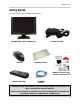
Getting Started Getting Started The system comes with the following components: POWER ADAPTER LCD MONITOR & DVR COMBO UNIT MOUSE CLEANING CLOTH MANUALS, QUICK START GUIDE & SOFTWARE CD REMOTE CONTROL ETHERNET CABLE * HARD DRIVE SIZE AND CAMERAS VARY BY SPECIFIC MODEL. PLEASE REFER TO YOUR PACKAGE FOR CONTENT DETAILS. CHECK YOUR PACKAGE TO CONFIRM THAT YOU HAVE RECEIVED THE COMPLETE SYSTEM, INCLUDING ALL COMPONENTS SHOWN ABOVE.
Tips & Tricks - Useful System Information Tips & Tricks - Useful System Information The following Tips & Tricks contain useful information about your System: • Your default System Password is 1234. This password may be required when entering menus, reviewing Recorded Data, Archiving, PTZ, and for Remote Access. You can change this password in the System Menu. • Make sure to set up your DATE & TIME prior to starting Recording. These settings are very important to maintain system data accuracy.
Tips & Tricks - Useful System Information Basic System Setup The following connections are recommended prior to loading the System for the first time.
Tips & Tricks - Useful System Information System Startup / Shutdown System Loading Sequence • Press the POWER button located on the front panel of the System to start the unit, or press the Power Button on the Remote Control. • The System will perform a Hard Drive check The unit will initially load to a split screen view, displaying all channels (if available). Empty channels will be displayed in Blue. NOTE: If a new HARD DRIVE is detected, the system will prompt you to FORMAT the drive.
Front Panel Front Panel 1 2 3 4 5 6 7 8 1. System Power Button 2. Multi-Function Modes 3. Setup Menu 4. Return Button 5. Navigation & Enter 6. Power LED 6. Recording LED 8. Network Connection LED 1. SYSTEM POWER BUTTON - Press the System Power button to turn the Monitor display ON/ OFF. Press and hold the button to turn the DVR ON/OFF. 2. MULTI-FUNCTION MENU MODES - Press the Multi-Function Menu button to switch between monitor modes: • DVR Mode - Displays the DVR with live camera view.
Front Panel Front Panel 1 2 3 4 5 6 7 8 1. System Power Button 2. Multi-Function Modes 3. Setup Menu 4. Return Button 5. Navigation & Enter 6. Power LED 6. Recording LED 8. Network Connection LED 4. RETURN BUTTON - Exits a menu and returns the screen to the default view for the selected Mode. 5. NAVIGATION & ENTER CONTROLS - Use the Navigation controls to move Up, Down, Left and Right in menus, and press Enter to select options. 6. POWER LED - Indicates that the system is ON/OFF (RED LED).
Rear Panel Rear Panel 1 2 9 3 10 11 4 5 6 7 8 12 1. DIN Video Inputs 2. BNC Video Inputs 3. VGA IN Port 4. Component Video IN 5. Component Audio IN 6. Relay / PTZ / RS-232 7. Ethernet 8. Power (DC 12V) 9. Audio Inputs 10. Spot Out 11. Audio Out 12. Alarm Block 1. 6 PIN DIN VIDEO INPUTS - Channel 1-4 Camera inputs (for cameras with 6 Pin DIN connections). Cameras with 6 Pin DIN connections draw power from the System - additional power adapters are not needed. 6 PIN DIN 2.
Rear Panel Rear Panel 1 2 9 3 4 10 11 5 6 7 8 12 1. DIN Video Inputs 2. BNC Video Inputs 3. VGA IN Port 4. Component Video IN 5. Component Audio IN 6. Relay / PTZ / RS-232 7. Ethernet 8. Power (DC 12V) 9. Audio Inputs 10. Spot Out 11. Audio Out 12. Alarm Block 10. SPOT OUT - Video Output port to connect the unit to a Monitor or TV.
Camera Installation Camera Installation Before you install the camera, carefully plan where and how you will position the camera, and where you will route the cable that connects the camera to the System. Installation Warnings: • Select a location for the camera that provides a clear view of the area you want to monitor, which is free from dust, and is not in line-of-sight to a strong light source or direct sunlight.
Camera Installation Connecting DIN Cameras 1. Connect the female end of the supplied DIN extension cable to the camera. * NOTE: Confirm that the arrows on the DIN Camera Cable and the DIN Extension cable are pointed together when connecting the cable. If the pins in the DIN Cable are bent, the Camera will NOT function. 2. Connect the male end of the supplied DIN extension cable to an open DIN camera input on the back of the System. Continue connecting additional DIN cameras.
Camera Installation Connecting BNC Cameras 1. Connect the Extension cable to the Camera and System: A. Connect the Barrel Power connector to a power adaptor. B. Connect the BNC connector to an available BNC Port of the System. C. Connect the Male Power connector to the Camera. D. Connect the BNC connector to the Camera. 2. Connect the Power Adaptor to a wall outlet. IMPORTANT NOTE: The ends of the extension cable are NOT the same - one end has a Male power port, and the other has a Female power port.
Multi-Function Display - Monitor Modes Multi-Function Display - Monitor Modes This system contains a multi-function display, which allows the system to function in several modes: • Mode 1: DVR Mode - Displays the DVR with live camera view. • Mode 2: VGA Mode - Displays the device connected to the VGA Port on the monitor (i.e. Computer). • Mode 3: Component Mode - Displays the device connected to the component green, blue, and red inputs (Y/Pb/Pr) in high resolution (i.e.
Digital Video Recorder (DVR) Mode (Mode 1) Digital Video Recorder (DVR) Mode (Mode 1) DVR Mode is the primary mode for the System, and is the displayed when the system is powered on. In DVR Mode, the system performs the following functions: • View and Record live video channels in Single, Quad, Multi-Display or Sequence Mode. • Customize the recording on up to 8 camera channels in continuous, motion or alarm recording modes.
DVR Mode - Remote Control Usage DVR Mode - Remote Control Usage 1. MODE: Press the Mode Button to display the Multi-Function Mode Menu. 2. POWER: Press the Power Button to turn off the Monitor Display. Press and hold the button for 3 seconds to shut down the entire system. 1 11 3. DVR: Change to DVR Mode. 2 12 3 13 6. NAVIGATION/PLAYBACK: Press the Navigation Controls to move Up, Down, Left or Right in System and Mode menus.
Front Panel Navigation Controls Front Panel Navigation Controls This System has been designed to use the Mouse or Remote Control as the primary modes of navigation and configuration for the system. The Front Panel buttons can also be used to access the menus and configure the system. • Navigation Controls - Move Up/Down/Left/Right in menus. • Press the Up or Down arrow keys (when in the default display mode) to load the On-Screen Display Menu (see next page for details).
On-Screen Display Menu On-Screen Display Menu The On-Screen Display Menu is accessed by either: • Pressing the Up or Down Arrows on the Front Panel • Right Clicking the Mouse The Menu options include: 1. CHANNELS: Select a Channel Number (1~8) to display a camera in Full Screen Mode. 2. SETUP: Displays the System Setup Menu. Please refer to the System Setup section for detailed configuration. 3. SEARCH: Allows you to locate previously recorded video by Date and Time, or by Event Type. 1 2 4.
System Display System Display Camera Title: The title for the camera is displayed in the upper left corner of the channel window, to a maximum of 11 characters. To change the name, use the System Setup options. Recording Status: : Record : Pre Record C: Continuous M: Motion A: Alarm Date & Time: Displays the current Date and Time for the System. NOTE: It is very important to set the Date and Time prior to recording.
System Display Camera Display Modes Cameras can be displayed in several different modes by pressing the Display Button on the Remote Control or Mouse Menu. A Display Selection window will appear onscreen. Select from the available display types: Single Channel Quad (4) Channel 8 Channel Split View 8 Channel (Grid) Zoom Mode • Displays the Camera in ZOOM Mode. • Use the Arrow keys to adjust the Zoom location. • Press the Return key to exit ZOOM Mode.
System Display PIP Mode (Reverse PIP) When using the PIP function when viewing in DVR MODE, it is referred to as ‘Reverse PIP’ (as normal PIP means displaying the DVR Screen as a PIP on any other mode). Select the PIP Button to display the VGA or Component mode in a PIP window. This function could be used to watch a Movie will still monitoring the Live Video display.
Menu Navigation Controls & Tips Menu Navigation Controls & Tips YOUR SYSTEM PASSWORD IS: 1234 Virtual Keyboard Control The Virtual Keyboard control becomes available when keyboard input is needed for entering information such as Names, Network Information, etc. • Includes a~z, A~Z, 0~9 and Symbols.@#$%^&*() • Navigate using the arrow keys on the Front Panel or Remote Control, or by clicking with the Mouse. • Select the ENTER button once the Alpha/Numeric entry is completed.
System Setup Controls System Setup Controls • Enter the MENU screen by pressing the SETUP button on the Remote Control, by pressing the SYSTEM MENU button on the Front Panel or by selecting SETUP from the Mouse Menu. Enter the password (if required). The default password is 1234 Main Menu DISPLAY - Setup of display options. CAMERA - Setup for individual Cameras. SOUND - Sound settings for the System. SYSTEM - System and Network settings. EVENT/SENSOR - Alarm and Event setup.
Display Menu Display Menu The Display Menu controls: OSD (Onscreen Display) • Status Bar - Turns the status bar ON/ OFF. The status bar displays: z z z z z Recording State (Recording: Red, Pre-recording: Green) Network Indicators Time and Date % HDD Free Refer to Recording Settings on page 50). • Camera Title - Turns the display of the Camera Titles ON/OFF. • Event Icon - Turns the Event Icon display ON/OFF.
Display Menu MONITOR SEQUENCE • Sequence Dwell - Sets the cycle time when the system is in Sequence Mode (between 1~60 seconds). • Spot-Out Dwell -The length of time to display a camera in Spot-out mode. • De-Interlace Mode - Removes the screen spread when set to ON. • Alarm Pop-Up Mode - Set to ON/OFF. Switches the screen display to the detected channel when an Alarm is activated. Sets the Sequence Mode for the display of available channels.
Display Menu Once the New Sequence has been created, the Sequence Setup Mode screens appear. These screens will set the sequence patterns (see the following for details). Modifying a Sequence • An existing Sequence can be Modified by selecting it from the list, and pressing ENTER. Once changes have been made, select the MODIFY button to configure the views, then press the SAVE Button. SEQUENCE SETUP - REMOTE 1. Press the ENTER button on the Remote.
Display Menu 5. Press the RETURN button when complete. and select SAVE & EXIT. 6. Press the SEQUENCE button on the Remote or Mouse Menu to switch to Sequence display. SEQUENCE SETUP - MOUSE 1. Double Left Click on the Green Highlighted box. The Highlight will change to YELLOW - Setup Mode is now active. 2. Select the Display Mode by single left clicking to switch (5 different Display Options - Single, Quad, 6-split, 8-split & 8-quad). 3.
Display Menu • Check or Uncheck the selected Cameras to have the video sent to a Secondary Monitor in Sequence. NOTE: Any cameras NOT selected will not be sent as video to the Spot Out Monitor. SCREENSAVER 5. Right click an empty spot outside of the squares when complete. and select SAVE & EXIT. 6. Press the SEQUENCE button on the Remote or Mouse Menu to switch to Sequence display. SPOT-OUT Sends the Specified camera video to a secondary Monitor (using the Spot Out Port on the back of the unit).
Camera Menu Camera Menu The Camera Settings and Controls: CAMERA TITLE - Settings for the onscreen display of individual Camera Titles. COLOR SETUP - Color settings for individual cameras. PTZ SETUP - Configuration for PTZ type cameras (not included with the system). MOTION SENSOR - Configuration for Video Motion Detection. CAMERA TITLE • Covert - Turns the onscreen display of the Camera ON/OFF. Covert Cameras continue to record, however the camera is not displayed onscreen.
Camera Menu COLOR SETUP PTZ SETUP Displays the settings for Brightness, Contrast, Tint and Color for individual cameras. PTZ Setup is for PTZ Type Cameras ONLY, which are not included with this system. For more information on PTZ Cameras, visit us on the web at http://www.lorexcctv.com. • Press the ENTER Button and select a camera setting‘. • Set the Brightness, Contrast, Tint and Color for each camera.
Camera Menu PTZ PROPERTIES MOTION SENSOR • Sensitivity - Controls the Motion Sensitivity for the individual camera between 1 (low) ~ 10 (high). • Area Setup - Opens the Area Setup for the camera: Selected Areas are shaded in BLUE. • Channel No. - Camera Number. • PTZ Driver - The compatible driver selected for the PTZ Camera. • Auto Focus - Sets the Automatic camera focus to ON/OFF. • Auto Iris - Sets the Automatic Shutter to ON/OFF.
Sound Menu Sound Menu The System Sound settings: AUDIO - Settings for the system Audio for Live and Remote monitoring. BUZZER - Settings for System Buzzer (audible alerts). SOUND • Live Audio - Turns Live System Audio (from the Audio on the terminal) to ON/ OFF. • Audio Monitoring Channel - Select the channel for Listen-in Audio (Channels 1~4 ONLY). NOTE: Listen In Audio only works with Channels 1~4. Other channels will send audio which will be Recorded.
System Menu System Menu The System Setting controls contain: DATE/TIME - Date and Time controls for the system. NETWORK - Network and remote access controls. MAIL - Mail setup USER MANAGEMENT - Controls for system users. SYSTEM MANAGEMENT - System specific settings and controls CONTROL DEVICE - Settings for an external control device (such as a PTZ Keyboard). DATE/TIME • Date/Time - Sets the current system Date and Time.* • Date Format - Sets the Date Display format (MM-DD-YYYY, YYYY-MM-DD, etc.).
System Menu NETWORK • Web Service - Allows the unit to be remotely accessed using Internet Explorer. This setting can be set to ON/OFF. • Max TX Speed - Sets the default Maximum Data Transfer speed for the remote connection (default of 8192 KB/sec.). • Network (TCP/IP) Settings: • IP Address - The IP address assigned to the System. • Gateway - The network Gateway assigned by the Router (or manually entered).
System Menu MAIL SETUP • Default Server - Check to use the Default SMTP server provided by Lorex. Uncheck this option to configure the options using your own mail settings. NOTE: You must sign up for the Lorex DDNS to use the Lorex Mail Server. The following settings are only needed if you are NOT using the Lorex Mail Server. Uncheck the ‘Default Server’ box to access the following: • SMTP Server - Enter the Email server information for your IP.
System Menu SYSTEM MANAGEMENT System Information Screen • IP Address - Displays the IP address assigned to the System. • System Information - Navigate to the PRESS button, and choose ENTER to display the System Information. To display the System Information from the main Channel view screen, press the ENTER Key on the front Panel -or- Press the INFO button on the Remote Control. • System Name - Input a name for the system using the Virtual Keyboard.
System Menu The firmware on the unit can be updated via the USB Port: • Download the new firmware from the website. Copy the files from the PC to the USB Memory Stick. • Insert the Memory Stick into the System. Select the ‘Firmware Update’ option by selecting the PRESS button. • The System must be restarted for the Changes to Take effect. Press OK, and exit the Menu. The System will automatically Reboot.
System Menu Factory Defaults The System can be returned to the Factory default settings: If the device is not detected, a message will indicate that No storage device was found. z • Select the ‘Factory Defaults’ option by selecting the PRESS button. • Choose OK to reset the unit, or CANCEL to exit without resetting. • Insert the Memory stick into the System and select the Load option to restore settings.
Event / Sensor Event / Sensor The Event Sensor Setting controls contain: HDD EVENT • Smart Alarm - Sets the Smart Alarm ON/ OFF. An alarm occurs when errors are detected with the drive. • Check Interval - Sets the Hard Drive check interval (1~24 hrs). This setting allows the System to self-check the drive for any errors, and generate an Alarm if drive errors are found. HDD EVENT - Checks the Hard Drive for errors. ALARM INPUT Configurations for any external alarm device (i.e. a Door or Window Sensor).
Event / Sensor ALARM OUT BUZZER OUT Sends an Alarm Out signal to a device (such as a Manual Door or independent Light/ Buzzer Alarm) when an Alarm In event is detected Generates a Buzzer when an alarm is detected. • Operation - Enables / Disables the buzzer for selected Event / Alarm types. Set to ENABLE to change the following settings: • Channel - Indicates all channels. • Operation - Setup Relay Connect with Alarm Sensor to either Enable or Disable. Must be ENABLED to change the settings manually.
Disk Management EMAIL NOTIFICATION Disk Management Sends an email to the specified users when the following events occur: • Notification - Sets the E-Mail notification ON/OFF. • HDD Event - A notification is sent if a Hard Drive event is detected (set to ON/ OFF). • Notifications can be enabled for each channel for: z z z Alarm Video Loss Motion can be selected NOTE: Emails will be sent at 5 minute intervals for the duration of the Event.
Disk Management • Format - Erases all Hard Drive data: Press start button. A warning message will be displayed with the prompt ‘All Recorded Data will be erased.’ z Select OK to erase the data, or CANCEL to return without erasing the Hard Drive. z • Once OK is selected, the user will be prompted to enter the ADMIN PASSWORD. Once the password is accepted, all Hard Drive data will be erased. Formatting Status Indicator Window: Once the format is complete, the system will return to the Disk Manage Menu.
Recording Menu Controls Recording Menu Controls • Enter the RECORDING MENU screen by: z z z Pressing the SETUP button on the Remote Control Pressing the SETUP button on the front panel, or Selecting the SETUP option from the On-Screen Menu. Enter the password if required using the Virtual Keyboard.
Simple Recording Mode Once the settings have been changed, a status window will appear indicating that the changes have been saved. Choose the OK button to close the status window and return to the Main Menu. Simple Recording Mode Recording Operation The Recording Operation Menu allows the user to switch between Simple and Advanced Modes. The settings for Schedule Mode, Pre-Event Recording Time and Post-Event Recording Time cannot be changed. These settings can only be configured in Advanced mode.
Simple Recording Mode Simple Recording Mode Select a single or multiple time blocks: • Mouse Control: Click a single block to open the Recording Type Menu. Click and Drag a block of times to configure multiple channels and times at once.
Advanced Recording Advanced Recording Continuous / Motion Setup The Continuous/Motion Setup section controls the Recording settings for each camera individually (quality, resolution, frame rate and audio). Both Continuous (constant recording) and Motion (recording when motion has been detected by the system) are set in this menu.
Advanced Recording Continuous / Motion Schedule Sets the Time or Motion recording for each channel (by hour). Select single or multiple time blocks: Select from: • NONE: Recording is turned OFF. • CONTINUOUS: Recording is always ON. • MOTION: Only starts the recording if motion is detected in the selected time interval.
Advanced Recording Advanced Recording Alarm Setup Mode The Alarm Setup section controls the Recording settings for each camera individually (quality, resolution, frame rate and audio). Recording Settings for external alarm detection are set in this menu. Alarm Parameter Select an Hour (highlighted in ORANGE), and press ENTER again to open the Camera Settings for the selected hour, or select multiple blocks in a row and press ENTER.
Advanced Recording Alarm Schedule Sets the Alarm Recording for each channel (by hour). Select single or multiple time blocks: • Mouse Control: Click a single block to open the Recording Type Menu. Click and Drag a block of times to turn Alarm Recording ON or OFF. • Remote Control & Front Panel: Navigate to the Channel Block section, and the entire block will be highlighted with a White outline: Press the ENTER button to access the Time Blocks - the first hour on Channel 1 will be highlighted in Yellow.
Archiving Archiving Archiving Options The Archive feature copies data from the Hard Drive to a USB backup media (such as a Memory Stick or USB Hard Drive), optical drive (CD-RW / DVD-RW) or FTP.‘ NOTE: Make sure that you have removed all data from the USB device prior to backup. • Enter the ARCHIVING screen by pressing the MENU button. Enter the password, and select the ARCHIVING option.
Archiving Archiving Options Once the Start Time, End Time and Channel Selections have been completed, select the START Button A Drive Usage report will be displayed including Amount of space (in MB) needed, Start and End Times for Each Channel, with size of recordings (in MB) and Size of the Log File The Erasing status window displays the completion state of the Erasing of previously archived data (in%) Error Messages Select OK to begin the backup The Writing status window displays the completion state
Archiving Archive Backup to FTP A schedule for data backup to a local or remote FTP can be configured on the System. 1. Choose FTP from the ‘Select Device’ dropdown menu. 2. Press the FTP Button to access the FTP Settings: • Port: Enter the Port used to connect to the FTP Site. Press the FTP Test button to test the connection to the FTP site. A ‘Success’ or ‘Fail’ message will appear.
Search Search Search mode allows you to locate previously recorded video by Date and Time, or by Event Type. • Press and Hold the arrow keys to select the Time (increments of 1 minute). Pressing the button without holding will increment 15 minutes. • Press the Search Button on the Remote Control or Mouse Menu. Any days highlighted with GREEN indicate that there is recorded video data. • Enter the User Name and Password (if required).
Search Search By Event Searches the system based on Event Type (Alarm, Motion, Continuous or System). • Press the right arrow button on the front panel or remote control to access the Search By Event screen. • Select From and To dates, Events (Alarm, Continuous, Motion and Other) and Cameras • Navigate within the options using the Arrow Keys on the front panel or remote control. Press the Enter button to select or deselect options (Note: Multiple event types can be selected).
VGA Mode (Mode 2) VGA Mode (Mode 2) VGA Mode is used to display a device (i.e. a Computer) connected to the VGA Port on the monitor. To view a Computer using the Monitor: 1. Connect the PC to the Monitor using a VGA Cable. NOTE: VGA Cable is not included with the system. 2. Switch the Monitor to VGA mode using the Multi-Function Mode Button on the front of the Monitor, or by pressing the VGA Button on the Remote Control. NOTE: Press the PIP button to display the DVR in the bottom right corner.
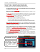
VGA Mode - Remote Control Usage VGA Mode - Remote Control Usage Listed below is a quick reference for the Remote Control usage in VGA Mode. 1. MODE: Press the Mode Button to display the Multi-Function Mode Menu. 2. POWER: Press the Power Button to turn off the Monitor Display. Press and hold the button for 3 seconds to shut down the entire system. 3. DVR MODE: Return to DVR Mode. 4. VGA MODE: Change to VGA Mode. 1 8 2 3 9 4 10 5 11 5. RETURN: Exits from a System Menu. 6.
Component Mode (Mode 3) Component Mode (Mode 3) Component Mode is used to display a device connected to the Component green, blue, and red inputs (Y/Pb/Pr) in high resolution (i.e. DVD Player, Set Top Box or Satellite Receiver). The Audio from the Component Device is connected to the Red and White audio inputs located to the right of the Component inputs. To view a DVD Player using the Monitor: 1. Connect the DVD Player to the Monitor using a Component Cable.
Component Mode - Remote Control Usage Component Mode - Remote Control Usage Listed below is a quick reference for the Remote Control usage in Component Mode. 1. MODE: Press the Mode Button to display the Multi-Function Mode Menu. 2. POWER: Press the Power Button to turn off the Monitor Display. Press and hold the button for 3 seconds to shut down the entire system. 3. DVR MODE: Change to return to DVR Mode. 4. VGA MODE: Change to VGA Mode. 5. RETURN: Exits from a System Menu.
Picture Frame Mode (Mode 4) Picture Frame Mode (Mode 4) Picture Frame Mode is used to display JPG images located on a USB Thumbstick (connected to a USB Port on the side of the monitor). To view a JPG Images using Picture Frame Mode: 1. Connect a USB Thumbstick containing JPG images to the Monitor, using one of the USB ports located on the side. NOTE: A USB Thumbstick is not included with the system. 2.
Picture Frame Mode - Remote Control Usage Picture Frame Display Images will be displayed in Picture Frame Mode (based on the Menu settings). NOTE: Press the PIP button to display the DVR in the bottom right corner. Picture Frame Mode - Remote Control Usage Listed below is a quick reference for the Remote Control usage in Picture Frame Mode. 1. MODE: Press the Mode Button to display the Multi-Function Mode Menu. 2. POWER: Press the Power Button to turn off the Monitor Display.
Picture Frame - Menu Picture Frame - Menu Insert the USB Thumbstick into the USB Port on the monitor prior to starting Picture Frame Mode. If a USB Stick is not detected by the system, the following message occurs: NOTE: To display the Picture Frame menu, press the MENU Button on the front panel of the System or on the Remote Control. Picture Frame Settings Menu • Device: Displays information about the currently connected Image Device (USB Thumbstick).
Picture Frame - Menu Picture Resizing Application An application has been included on the Software CD to resize your JPG images to 1600x1200 (highest recommended size), and save them directly to the USB Thumbstick. 4. Select a location, and click on the Open button. 1. Launch the application from the Software CD. The Picture Resize window will be displayed. 5. Once the Source and Target have been set, click the Execute button to resize and save the file. A Success message will be displayed. 2.
Installation Guide Mode (Mode 5) Installation Guide Mode (Mode 5) The Installation Guide Mode is used to display the Installation Video included on the System drive. To view the Installation Video using the Monitor, press the Multi Function Mode button on the front of the Monitor, or press the Mode button on the Remote Control and selecting Installation Guide. You can pause, rewind and fast forward for step by step instructions using the remote control.
Installation Guide Mode - Remote Control Usage Installation Guide Mode - Remote Control Usage Listed below is a quick reference for the Remote Control usage in Installation Guide Mode. 1. MODE: Press the Mode Button to display the Multi-Function Mode Menu. 2. POWER: Press the Power Button to turn off the Monitor Display. Press and hold the button for 3 seconds to shut down the entire system. 3. DVR MODE: Change to return to DVR Mode. 1 2 3 6 4 7 4. VGA MODE: Change to VGA Mode. 5.
Monitor - Menu Settings Monitor - Menu Settings Color Submenu Press the Setup key on the remote control, or front panel of the System to enter the Monitor Setup Menu (when in VGA or Component Modes). The Monitor Setup Menu controls the behavior and look of the Monitor (i.e. changing the Brightness and Contrast will affect the Brightness and Contrast in all Modes). NOTE: The mouse cannot be used to change values in this menu.
Monitor - Menu Settings Display Settings • Display Image: Sets the image display to Auto or Manual. • Aspect Ratio: Set the Aspect Ratio for the monitor. • Display Position: Adjust the Horizontal and Vertical screen positioning. Use the Arrow keys on the Front Panel or Remote Control to select from Auto Configuration, Phase, Clock or Highlight Window. Use the enter key to access the Display Control or Scheme submenus. Change the values using the arrow keys and enter.
Monitor - Menu Settings PIP Settings PIP Color Controls Submenu Use the Up, Down, Left and Right arrows to adjust the settings for Brightness, Contrast, Hue and Saturation. Press the Enter button to set, and the Return button to exit the menu. Use the Arrow keys on the Front Panel or Remote Control to select from PIP, PIP Input Select, PIP Size and Blend. Use the enter key to access the PIP Position or Pip Color Control submenus. Change the values using the arrow keys and enter.
Monitor - Menu Settings Misc. Settings • OSD Position: Determines the position of the Onscreen Display window. Use the Up, Down, Left and Right arrows to adjust the location of the screen. Press the Enter button to set, and the Return button to exit the menu Use the Arrow keys on the Front Panel or Remote Control to access the OSD Configuration or VGA Factory Reset submenus. Change the values using the arrow keys and enter. • PIP Position Submenu OSD Transparency: Set transparency for the OSD Menu.
System Specifications - Appendix #1 System Specifications - Appendix #1 Monitor Specifications • 20.
System Specifications - Appendix #1 System Specifications - Appendix #1 DVR Specifications • 8 Channels with Pentaplex operation - View, Record, Playback, Back Up &Remotely Control the system simultaneously • MPEG4 Digital Video Compression - small file sizes without compromising video quality • Recording Frames Per Second (FPS): 240/200 (NTSC/PAL) @ 352X240 • Recording Resolution: 352x288(PAL) 704x480, 704x240, 352x240(NTSC), 704x576, 704x288, • Custom recording for each camera • Covert Camera - re
Lorex Client 4.0 Software Requirements - Appendix #2 Lorex Client 4.0 Software Requirements - Appendix #2 The Lorex Client 4.0 software (included with the System) has the following installation requirements. Minimum System Requirements: Operating System Windows 2000 Windows XP Home Edition Windows XP Professional Windows Vista (32-bit) Processor .Pentium 4 - 1.
Setting up Remote Viewing - Appendix #3 Setting up Remote Viewing - Appendix #3 Setting up the Remote Viewing Feature requires several steps. Networking skills are required to correctly configure the remote viewing functions. What do you need? • The LCD/DVR System. • A PC with the installed with the Lorex Client 4.
Setting up Remote Viewing - Appendix #3 Network Checklist The following checklist is provided to assist you in confirming that all steps have been successfully performed during Network Setup. Use this checklist in conjunction with the steps outlined on the following pages. 1. I have the following: • High Speed Internet • A Router • The Ethernet Cable provided with this system • The System • A PC with the Remote Access software installed 2.
Setting up Remote Viewing - Appendix #3 5. I have enabled PORT FORWARDING on my Router for: • Port 80 • Port 6100 NOTE: Each Router is different, therefore the port forwarding settings will vary by model. Please visit us on the web at http://www.lorexcctv.com/support for assistance with several of the most common router types. If your router is not listed, please refer to the manual that came with your Router, or your Router manufacturer for assistance. 6.
Setting up Remote Viewing - Appendix #3 System - IP & MAC Address The IP & MAC Addresses are necessary for DDNS Setup (for remote access to the System). To Locate the System information, Press the ENTER button on the Front Panel or Info on the Remote Control while viewing the Cameras. The System Info window will be displayed. IP Address MAC Address - OR 1. Press the Menu Button on the Front Panel or Remote Control, or right click with the mouse to access the Setup Menu.
Setting up Remote Viewing - Appendix #3 Network - Router Port Forwarding You will need to enable port forwarding on your Router to allow for external communications with your System for ports: • TCP/IP PORT 6100 • WEB PORT 80 Computers, Systems, and other devices inside your network can only communicate directly with each other within the internal network. Computers and systems outside your network cannot directly communicate with these devices.
Setting up Remote Viewing - Appendix #3 Network - Setting Up Your DDNS Account Lorex offers a free DDNS service for use with your System. A DDNS account allows you to set up a web site address that points back to your Local Network. The following outlines how to set up your free DNS account. 1. Navigate to http://www.lorexddns.net 2. Select the Create Account option from the list on the left side of the screen. 3. Complete the Account Information fields with your personal information.
Setting up Remote Viewing - Appendix #3 NOTE: Make sure to write down your information BEFORE clicking on the Create New Account link. This information is important for your System Setup. User Name: _______________________________________________ * Domain Name: _____________________________________________ Password: _________________________________________________ * Only the first part of the Domain Name is required for setup on the System. If the full Domain sent is myurl.lorexddns.
Setting up Remote Viewing - Appendix #3 There are two ways to find your DDNS Configuration information at a later date. 1. Review the Email sent to you by Lorex: Dear A, Thank you for activating your free Dynamic DNS account for your Lorex DVR Combo. Once you have set up your Lorex device and configured your network, you will be able to view your video images from anywhere in the world using the URL shown at the end of this message. When you visit the Lorex web site at: https://secure.lorexddns.
Setting up Remote Viewing - Appendix #3 2. Log into the Lorex DDNS Website at http://www.lorexddns.net and enter your Username and Password.
Setting up Remote Viewing - Appendix #3 System - DDNS SETUP Once the DDNS settings have been configured online, the information must be entered on the System to allow for remote connection via the Lorex Client 4.0 Software (or through Internet Explorer): 1. Access the Main Menu Setup screens, and navigate to the SYSTEM option. Press the ENTER button to access the setup. 2. Navigate to the NETWORK option. Press the Enter button to access the Network settings.
Setting up Remote Viewing - Appendix #3 Lorex Client 4.0 Software - Connection Manager The Connection Manager contains the setup information to allow the user to remotely connect to the System. Adding a Group Group - Right click on ‘Site’ to add a New Group. A group can represent one or more Systems. For Example, you may have more than one system in your office, so would name your group ‘OFFICE’. Each individual unit can then be configured separately for connection. Enter a name for the Group.
Setting up Remote Viewing - Appendix #3 Adding a Site (Individual Unit Configuration) DVR Information - Enter the information specific to the unit (refer to page 30 for setup instructions): • Name - Enter a name for the unit. • IP / Domain Name Enter the IP address or Domain Name for the System. This will vary depending on setup (Internal Network Connection or External Remote access through the Internet)- refer to page 30 for setup details. • Port - Set to 6100 by default.
Setting up Remote Viewing - Appendix #3 Lorex Client 4.0 Software - Remote Connection Once the site setup profile has been created, a connection can then be made to the System: 1. Select the Site profile from the Dropdown List. 2. Press the CONNECT button. The Connection Status window displays the state of the connection. Once a successful connection to the System has been made, the black screen view will switch to Live Camera View mode.
Using the Auto Email Feature - Appendix #4 Using the Auto Email Feature - Appendix #4 Setting up Email This System has the ability to automatically send email when an event is detected. To configure the automatic sending of Emails, the following Menu option setup is required: • System Menu - Mail • System Menu - User Management • Event/Sensor - Email Notification System Menu - Mail Navigate to the System Menu, and select the Mail Option.
Using the Auto Email Feature - Appendix #4 This is an example of the same type of required settings (formatted for Microsoft Outlook). SERVER (Outgoing SMTP) PORT (More Settings, change only if recommended by your Internet Provider) USER & PASSWORD SECURITY NOTE: This example is not required for the System to function correctly. This is used to illustrate the required settings (using another program). Testing the Mail Setup Press the TEST E-MAIL Button on the System.
Using the Auto Email Feature - Appendix #4 System Menu - Mail Navigate to the System Menu, and select the Mail Option. New users can be added to the System through the User Management screen, and existing users can be edited. The important features in the User Setup are the E-Mail address and E-Mail Notification: • Set the E-Mail to the desired Receiving Address. • Set the E-Mail Notification to ON. This must be set ON for the user to receive mail.
Using the Auto Email Feature - Appendix #4 Event / Sensor - E-Mail Notification Navigate to the System Menu, and select the Mail Option. • NOTIFICATION - Notification must be turned on for Automatic E-mail alerts to be sent. • HDD EVENT - Emails a notification to all active accounts when problems are detected with the Hard Drive. • ALARM / VIDEO LOSS / MOTION - Select the type of event for which you wish to trigger email notification: Alarm, Video Loss or Motion Detection (for each channel).
Recommended Tips for System Setup - Appendix #5 Recommended Tips for System Setup - Appendix #5 There are several tips outlined below that will assist you in setting up your system: Connecting and Mounting Cameras: 1. Connect the DIN Extension Cable to an open channel port on the back of the System. Make sure that the ARROW on the cable is pointing up. This will align the pins on the cable correctly with the port on the stem, preventing the pins from becoming bent and the cable from becoming inoperable.
Recommended Tips for System Setup - Appendix #5 Navigating within the System Menu (cont.) Menu Navigation Controls This System has been designed to use the Mouse or Remote Control as the primary modes of navigation and configuration for the system. The Front Panel buttons can also be used to access the menus and configure the system. • Navigation Controls - Move Up/Down/Left/Right. • Enter Button - Press this button to select and change the values in a menu option.
Recommended Tips for System Setup - Appendix #5 Changing the Date and Time Setting the correct date and time for your system is important. Once the date and time have been set correctly, it is highly recommended that you format your Hard Drive. 1. Enter MENU mode by pressing the MENU button on the front panel of the system, Remote Control or Mouse Menu. Select the SYSTEM SETUP Option. 2. Select the SYSTEM menu from the MAIN menu. Navigate using the up and down arrows on the front panel (or remote control).
Recommended Tips for System Setup - Appendix #5 Formatting the Hard Drive Formatting the hard drive after changing the date, and before beginning the recording of YOUR data is recommended, as the system is set to Automatically start recording when powered on (continuous recording setting). NOTE: Formatting the Hard Drive will erase any previously recorded data. This will NOT affect your system configurations. 1.
Recommended Tips for System Setup - Appendix #5 Camera Setup Each camera should be assigned a name that corresponds to its use (i.e. Dock1, BackDoor, Cash3, etc.). This name is displayed onscreen, and helps to identify the camera location easily. 1. Enter MENU mode by pressing the MENU button on the front panel of the system, Remote Control or mouse menu. Select the SYSTEM SETUP Option. 2. Select the CAMERA menu from the MAIN menu.
Recommended Tips for System Setup - Appendix #5 Screen Saver Settings The screen saver will black the screen during a defined interval. 1. Enter MENU mode by pressing the MENU button on the front panel of the system, Remote Control or Mouse Menu. Select the SYSTEM SETUP Option. 2. Select the DISPLAY menu from the MAIN menu. Navigate using the up and down arrows on the front panel (or remote control). Highlight the selection in Green, and press the ENTER button to enter the DISPLAY Menu. 3.
Recommended Tips for System Setup - Appendix #5 Backing up your System Configurations it is recommended to back up your system configurations to a Memory Stick. Configuring your system to meet your specific needs can be time consuming - having a backup of your settings will allow you to reset your unit with your personalized settings in the event of an unwanted change. 1. Enter MENU mode by pressing the MENU button on the front panel of the system, remote control or mouse menu.
Listen-in Audio - Appendix #6 Listen-in Audio - Appendix #6 There are 4 available DIN camera ports, 8 available BNC camera ports and 4 BNC Audio ports on the system - how many can be used for Listen-In audio, and how many can be used to record sound? How do I enable Listen-In Audio, and how do I set the Listen-in channel? Listen-In Audio is the ability to listen to live audio on ONE channel at a time, between channels 1~4. To listen to live audio on a channel: 1.
Playback Previously Recorded Data? - Appendix #7 Playback Previously Recorded Data? - Appendix #7 Search mode allows you to locate previously recorded video by Date and Time, or by Event Type. • Press the Search Button on the front panel, Remote Control or mouse menu. Enter the User Name and Password (if required). • Use the Left / Right arrows on the Front Panel or Remote Control to switch between the Search By Time and Search By Event screens. Search By Time Searches the system based on date and time.
Playback Previously Recorded Data? - Appendix #7 Search By Event Searches the system based on Event Type (Alarm, Motion, Continuous or System). • Press the right arrow button on the front panel or remote control to access the Search By Event screen. • Select From and To dates, Events (Alarm, Continuous, Motion and Other) and Cameras • Navigate within the options using the Arrow Keys on the front panel or remote control.
Setting Auto-Recording to OFF - Appendix #8 Setting Auto-Recording to OFF - Appendix #8 The system is set to automatically start recording when powered on. You may wish to change these settings to better suit your security needs. These settings can be changed for an individual camera on one time block, or can be set for multiple cameras for multiple time blocks. Setting An Individual Time Block 1. Enter MENU mode by pressing the MENU button on the front panel of the system, Remote Control or mouse menu.
Setting Auto-Recording to OFF - Appendix #8 Setting Multiple Time Blocks 1. Enter MENU mode by pressing the MENU button on the front panel of the system, remote control or mouse menu. Select the RECORD MENU Option. 2. Select the SIMPLE RECORDING MODE menu. Navigate using the up and down arrows on the front panel (or remote control). Navigate using the arrow keys 3. Select the Channel Menu (highlights the area in PINK). 4. Press the ENTER key to enter the configuration mode.
Setting up Motion Recording - Appendix #9 Setting up Motion Recording - Appendix #9 The system is set to automatically start recording when powered on in Continuous Mode. You may wish to change these settings to better suit your security needs by having the cameras start recording when MOTION is detected. These settings can be changed for an individual cameras on one time block, or can be set for multiple cameras for multiple time blocks. 1.
Setting up Motion Recording - Appendix #9 7. The Schedule Window will be displayed, with the Motion Time blocks displayed as highlighted boxes. 8. Press the Return Button several times to exit the Recording Menus. Remember to SAVE YOUR CHANGES! To check if the unit is recording in Motion, all channels should have a green box on the top right hand corner. When motion is picked up it will change to a red box with a yellow M.
Setting up Motion Recording - Appendix #9 Motion Area Setup • Select the Motion Sensor Menu: Use the System menu to configure the Motion Detection areas. Setting the motion detection areas are useful to mask in specific areas (i.e. Doors or Windows), so when movement is detected in these areas the System Recording will begin.
Using the Storage Calculator - Appendix #10 Using the Storage Calculator - Appendix #10 The Storage Calculator application is used to calculate the amount of recording time available on your Hard Drive, based on the System Recording Settings. This application is located on the Software Installation CD (provided with your System) 1.
Hard Drive Replacement - Appendix #11 Hard Drive Replacement - Appendix #11 The System comes with a pre-installed Hard Drive, however the unit will work with a replacement single Hard Drive (up to 750GB). NOTE: Make sure that the System is OFF and the power cable has been disconnected before changing the Hard Drive. Setting the New Drive to Master • Refer to the General Jumper Pin Setting on HDD Surface (generally located on a sticker on the top of the drive). • Set the Jumper Pin Set to Master (1 Drive).
Hard Drive Replacement - Appendix #11 New Hard Drive Format The New Hard Drive MUST be formatted. If a new HARD DRIVE is detected, the system will prompt you to FORMAT the drive. If you do not choose to format the HARD DRIVE, the drive will not be detected by the system. If you choose to FORMAT a drive in this way, the drive will no longer be readable by a regular PC without using the HARD DRIVE VIEWER software included on the CD provided with this unit.
Connecting a Spot-Out Monitor - Appendix #12 Connecting a Spot-Out Monitor - Appendix #12 A connection to a Spot-Out Monitor (not included with the System) can be made through the SPOT OUT Port on the back of the System. • SPOT OUT - Displays Cameras in Sequence mode, regardless of the display on the DVR (i.e Camera Views, Menus, Playback, etc.) to a TV or VCR. • Configure the Spot Out settings using the System Menu controls (when in DVR Mode).
Connecting Motion / Alarm Device - Appendix #13 Connecting Motion / Alarm Device - Appendix #13 Motion detection and Alarm controls are enabled through the Menu system on the System. Additional motion sensor devices can be connected to the system (Motion Sensors, Door/ Window Sensors). A motion detection or sensor unit can be used to send a signal to the System to begin camera viewing on the matching Video Channel (when enabled in the Menu).
Connecting PTZ Cameras - Appendix #14 Connecting PTZ Cameras - Appendix #14 PTZ Cameras (not included with this system) can be connected to the PTZ Control Block on the back panel of the System. The PTZ Controls are enabled through the Menu system on the System. Additional PTZ Cameras are available at http://www.lorexcctv.com Installing a PTZ (RS-485 Type) PTZ Camera: 1. Connect the Transmit Cable to the D+ port on the PTZ Control Block on the System. 2.
Full Connectivity Diagram - Appendix #15 Full Connectivity Diagram - Appendix #15 The following diagram outlines a general set of connections available with the System.
Optional Accessories Optional Accessories The following accessories are available to add to your existing system: TO ORDER THESE ITEMS, AND FOR A COMPLETE LISTING OF AVAILABLE PRODUCTS, PLEASE VISIT US ON THE WEB AT HTTP://WWW.LOREXCCTV.
It’s all on the web Product Information Specification Sheets User Manuals Software Upgrades Quick Start Guides Firmware Upgrades VISIT www.lorexcctv.com www.lorexcctv.com Lorex Technology Inc.