23 & 27 & 32-INCH TFT-LCD PUBLIC VIEW MONITOR INSTRUCTION MANUAL Please read this manual thoroughly before use, and keep it handy for future reference.
………………………………………………………….…… 2~3 …………………………………………………………….......................... 4 ……………………………....................... 5 ……………………………………………………………............................... 6 CONNECTING WITH EXTERNAL EQUIPMENT …..………………………………… 7 ………………………………………………………………… 8 ……………………………………………………….. 9 ~ 18 CAMERA CONTROLS AND FUNCTIONS …………………….……………………….. CARD READER CONTROLS AND FUNCTIONS …………………………………….. MOUNTING GUIDE ……………………………………………………………………..
Important Safety Instruction 1. Read these instructions. 2. Keep these Instructions. 3. Heed all warnings. 4. Follow all instructions. 5. Do not use this apparatus near water. 6. Clean only with dry cloth. 7. Do not block any ventilation openings. Install in accordance with the manufacturer‟s instructions. 8. Do not install near any heat sources such as radiators, heat registers,stoves, or other apparatus (including amplifiers) that produce heat. 9.
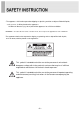
- The apparatus shall not be exposed to dripping or splashing and that no objects filled with liquids, such as vases, shall be placed no the apparatus. 14 Minimum distances(e.g. 10cm) around the apparatus for sufficient ventilation. “WARNING – To reduce the risk of fire or electric shock, do not expose the apparatus to rain or moisture.” “The apparatus shall not be exposed to dripping or splashing and no objects filled with liquids, such as vases, shall be placed on the apparatus.
CAUTION The power supply cord is used as the main disconnect device, ensure that the socket-outlet is located/installed near the equipment and is easily accessible. ATTENTIONN Le cordon d`alimentation est utillsé comme interrupteur général. La prise de courant doit être située ou installée à proximité du matériel et être facile d`accès ▶ NEVER REMOVE THE BACK COVER Removal of the back cover should be carried out only by qualified personnel.
NOTE This equipment has been tested and found to comply with the limits for a Class A digital device, pursuant to Part 15 of the FCC Rules. These limits are designed to provide reasonable protection against harmful interference in a residential installation. This equipment generates, uses and can radiate radio frequency energy and, if not installed and used in accordance with the instructions, may cause harmful interference to radio communications.
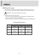
WIRING (only 24V~ inputs) 1. On the back of the monitor, loosen the thumb screws and lower the access panel. 2. Attach the leads from the power supply (not supplied) to the left and right connectors. WARNING: Do not connect a ground to the center post. 3. When finished, secure the access panel. Table A shows the recommended maximum wiring distances (transformer to load), and are calculated with a 10-percent voltage drop. (10 percent is generally the maximum allowable voltage drop for AC-powered devices.
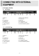
1. TOP PANEL CONTROL 1-1. AC IN Type 1 2 3 4 5 6 7 8 9 10 11 1. HDMI1 IN 2. MEDIA PLAYER (HDMI2 IN) 3. DVI 4. VGA (RGB PC) 5. PC STEREO IN 6. AUDIO OUT 7. CAMERA OUT 8. AV2 (VIDEO2) IN 9. AV2 (VIDEO2) OUT 10. IP CAMERA ETHERNET 11. USB 2.0 (Optional) 12. SD CARD READER (Optional) 12 13 13. AC IN 1-2. AC 24V IN Type 1 2 3 4 5 6 7 8 9 10 11 1. HDMI1 IN 2. MEDIA PLAYER (HDMI2 IN) 3. DVI 4. VGA (RGB PC) 5. PC STEREO IN 6. AUDIO OUT 7. CAMERA OUT 8. AV2 (VIDEO2) IN 9.
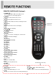
REMOTE CONTROLLER (Optional) 1. POWER( ) Turns the power ON or OFF. There will be a few seconds delay before the display appears. 2. SOURCE Selects pc or video(Camera, AV) sources. 3. AUTO Auto geometry adjustment in PC Source. 4. HOLD Stops the Motion Detection & Auto switching functions. 5. MUTE Not operating. 6. MENU Activates and exits the On Screen Display. 7. EXIT Exits the On Screen Display. 8. VOL(◀ & ▶) Accepts your selection. 9. UP/DOWN Moves to OSD menu. 10.
FRONT & BACK KEY CONTROL 6 7 8 9 10 11 12 1 2 345 1. MOTION DETECTION Built-in camera sensor for the Motion detection function. 2. BUILT-IN CAMERA Image of this camera is shown by HDMI. 3. IR Sensor Remote controller sensor. 4. POWER LED The power LED lights with green when the power is turned ON. The power is turned off by pressing the power switch again and the power LED goes to off. 5. RECORDING INDICATOR LED This LED indicates the recording status by blinking the LED light.
OSD MENU DESCRIPTION All picture, sound settings and setup for the monitor can be adjusted in the OSD menu. (On Screen Display) To adjust the OSD screen: 1. Press the MENU button to enter the OSD menu. 2. Press the ▲/▼ buttons to select the desired option. The selected option is highlighted. 3. Press the ▶button to enter the submenu for adjusting items. 4. Change the value you wish to adjust by using the ◀/▶ buttons. 5. Press the ◀button to exit the submenu for adjusting items. 6.
B. Picture/Sound Option Function Value Picture Mode Sets picture mode. See table below Color Tone Sets color tone. See table below Mute Mutes speaker sound. Off or On Volume Adjust the level of audio volume. 0 ~ 100 Size Display picture size. See table below Reduces noise of the picture. On or Off Activates the 3D comb filter. On or Off See table below. See table below Date Time Sets the date time on the screen.
Color Tone Cool Gives the white color a bluish tint. Normal Gives the white color a neutral tint. Warm Gives the white color a reddish tint. User To manually adjust the color tones(Red, Green, and Blue).
Date Time Option Function Value Date Time Activates the feature of Date Time. Off or On Blink This function is for blinking Date & Time texts. Off or On OSD Position Selects the location of Date Time text. Top, Bottom Year* Selects the wanted year. 2000~2100 Month* Selects the wanted month. 1~12 Day* Selects the wanted day. 1~31 Hour* Selects the wanted hour. 0~23 Minute* Selects the wanted minute.
Recording Text Option Function Value Recording Text Activates the feature of Recording Text. Off or On Text Blink This function is for blinking Recording text. Off or On Text Size Selects the size of Recording text. X1, X2, X3 Text Select Selects the wanted phrases.
C. PIP Option Function Value PIP Activates the PIP feature. Off or On Input Source Selects the input source for the PIP area. See table below PIP Mode PIP Size Position Enables 3 screen size.4:3 side by corner, 4:3 side by 4: 3, and full screen side by side. Selects the size of PIP screen. PIP, PBP1 or PBP2 Size1, Size2 or Size3 Selects the position of PIP screen. Right of Bottom, Left of Bottom, Left of Top and Right of Top.
D. Setup Option Function Value Resets the monitor settings to their Reset factory default. English, French, Deutsch, Language Sets the language of the OSD menu. Italian, Spanish, Portuguese or Nederland Changes background of monitor menus. OSD Tone (e.g. input source & information) Displays a blue screen if the monitor Blue Screen receives no signal. Locks all buttons of the monitor. Key Lock Note: Use remote controller to unlock.
Motion Detection Option Function Detection Enable Activates the Motion Detection feature. Detection Input Selects the input source for the Motion Detection. Buzzer Activates an audible signal when the monitor receives a motion detection signal. Value Off or On Camera, AV2, RGB PC, DVI, HDMI1, M/P(HDMI2) On or Off Selects the amount of time, in seconds, Detection Time that the monitor displays the motion detection 3 ~ 100 input image. Detection Option Not operating.
Auto Switching Option Auto Switching Input Enable Time Function Value Activates the Auto Switching feature. Off or On Opens another menu and you can select the input Camera, AV2, RGB PC, DVI, sources to include in the Auto Switching cycle. HDMI1, M/P(HDMI2) Selects the amount of time, in seconds, that the monitor displays each selected input source.
Setting up the menu Settings can be made using the OSD Switch located on the back of the camera. 1. Press the button to access the SETUP mode. The SETUP menu is displayed on the monitor. 2. Please select any function you wish to activate by using the UP/DOWN selections. The cursor can be moved up or down by using the UP/DOWN selections. Position the cursor to point to the function you wish to operate. * MAIN-menu: Use UP/ DOWN selections. / SUB-menu: Use LEFT/ RIGHT selection 3.
1-2. EXPOSURE (1) SHUTTER - Shutter speed control (AUTO&FLK level: 1/60~1/100000/X2~X60) (2) AGC (Auto Gain Control) The higher the gain level is, the brighter the screen becomes. But the higher gain level causes more noise. - LOW: Allows automatic gain control from 0 to 20dB. - MIDDLE: Allows automatic gain control from 0 to 30dB. - HIGH: Allows automatic gain control from 0 to 42dB. - OFF (3) SENS-UP - The Sens-up function allows the camera can display the bright image even extreme darkness.
(6) DEFOG - Images in extraordinary environment such as fog or rain or in a very strong luminous intensity have DR (dynamic range), lower than ordinary images. (7) BACKLIGHT - BLC controls the brightness level of the screen in order to be able to distinguish objects against backlight. - HSBLC It cuts off the strong lighting like the “headlight”. According to user‟s adjustment, zones & sensitivity can be adjustable.
1-3. WHITE BAL (1) MANUAL - In the manual mode, the user can choose the color and temperature. The user can adjust the color and temperature by controlling red and blue gain. (2) AWC→SET - This is used in order not to change the color and temperature values set for a certain environment. Press for two to three seconds the “Set Button” on the OSD MENU in order to have the color and temperature values fixed.
1-4. DAY & NIGHT You can display pictures in BW/AUTO/COLOR (1) B/W Mode - B/W Mode is used to maintain B/W mode all the time. - BURST - IR SMART - IR LED - IR PWM LEVEL 0~100 (2) Auto Mode - Automatically turns between Day and Night Mode according to AGC operation. (3) Color Mode - COLOR Mode is used to maintain color mode all the time.
1-5. NR (NR) Noise Reduction is used in order to obtain a high quality output image and enhance compression efficiency. We offers Edge Preserving 2DNR and Motion Adaptive 3DNR. 3DNR level reduces more low light noise but it can cause ghost effect as well. (1) 2DNR (2) 3DNR ON S-LEVEL 0~100 E-LEVEL 0~100 (3) LEVEL 0~100 (4) SMART NR 1-6. SPECIAL (1) CAM TITLE - To display a title on the monitor (2) D-EFFECT - FREEZE: To hold a stop picture.
(3) MOTION - The feature allows you to integrate your cameras with external devices - to engage that device upon the detection of motion. Common devices include security lights, alarms, access control devices, and more. (4) PRIVACY - Privacy masking allows masking a certain spot on the screen. We offer a total of 8 Privacy Masking Windows.
1-7. ADJUST - SHARPNESS ON/OFF / LEVEL 0~100 / RESOLUTION ON/OFF - MONITOR GAMMA 0.45~USER LCD BLUE GAMMA 0~100 RED GAMMA 0~00 BLACK LEVEL-30~+30 CRT BLUE GAIN 0~100 RED GAIN 0~100 - OSD TEXT COLOR 1~8 OUT LINE ON/OFF - LSC - NTSC/PAL 1-8. RESET - FACTORY - Resets the camera setting to the factory defaults. - RETURN 1-9.
2. IP PVMZ Installation and Basic Setup 2.1. Before Installation - Read carefully User's Manual. - Check User‟s Network (IP Address, Network Mask and default gateway) - Secure IP address for IP PVMZ. 2.2. Factory Default Settings The following table shows the factory default condition. Please refer to this when you need to change the values on admin menu. Factory Default Admin ID root Admin password root IP address 10.20.30.40 Network mask 255.255.255.0 Gateway 10.20.30.
Menu of the M/P (Media Player) • Connect USB & SD card devices 1. Connect USB & SD card devices to USB slot which are on the slide of the monitor set. • Removing the USB & SD card devices from Monitor 1. Return to main menu and press ESC. 2. Remove the USB & SD card devices from Monitor. - Entering Card Reader, displaying main menu. [MUSIC] [MOVIE] [MUSIC PHOTO] Option Function PHOTO Displaying photo and slideshow. MUSIC Playing music in the USB device.
A. PHOTO JPEG File Viewing Options - When you select Photo in entry menu, 1. Press the USB button and then use ◀/▶ button to select the Photo. 2. Press the SEL button. 3. Press the ▲/▼ button to select photo file. 4. Press the SEL button for 1 picture display for slideshow. 5. Press exit or press the ESC button to return to the USB menu. Slideshow 1. Press ◀/▶ button to select the Photo. 2. You can choose the slide show effect, frequency and play mode in the USB Setup. 3.
B. MUSIC - Purchased MP3/music files may contain copyright restrictions. 1. Press ◀/▶ button to select the Music. 2. Press the SEL button. 3. Press the ▲/▼ button to select desired music file. 4. Press the SEL button. Then the music starts. 5. Press exit or press the ESC button to return to the USB menu.
C. MOVIE - Select the Movie 1. Press ◀/▶ button to select the Movie 2. Press the SEL button. 3. Press the ▲/▼ button to select desired movie file. 4. Press the SEL button. Then the movie starts. 5. Press exit or press the ESC button to return to the USB menu.
D. PHOTO MUSIC -Playing slideshow with music. 1. Press the USB button and then use ◀/▶ button to select the PHOTO MUSIC. 2. Press the SEL button. 3. Press the ▲/▼ button to select photo file. 4. Press the SEL button for picture display for slideshow. 5. Moved to music file list for music playing. 6. Press the SEL button for playing music with photo slide show. 7. Press exit or press the ESC button to return to the USB menu.
E. PHOTO Thumbnail mode - Thumbnail mode in photo. - Press ▶ button in Photo File list or ACT button in main menu 1. Press ▲/▼/◀/▶ button to select desired photo file. 2. Press SEL button to start Slideshow 3. Press exit or press the ESC button to return to the USB menu.
F. SETUP 1. SETUP- PHOTO Select Slideshow Effect -The picture display effect for the slide show. 1. Press ◀/▶ button to select the Setup. 2. Press the SEL button enter the Setup menu. 3. Press the ▶ and then use ▲/▼ button to select Slideshow EFFECT. 4. Press the ▶ and then use ▲/▼ button to select the desired Effect. 5. Press exit or press the ESC button to return to the USB menu. Select Slideshow Speed -The picture display interval for the slide show. 1. Press ◀/▶ button to select the Setup. 2.
2. SETUP-SYSTEM Select SUBTITLE LANG. - The menus can be shown on the screen in the selected language. First select your language. 1. Press ◀/▶ button to select the Setup. 2. Press the SEL button to enter the Setup menu. 3. Press the ▲/▼ button to select the SYSTEM SETUP. 4. Press the ▶ and then use ▲/▼ button to select SUBTITLE LANGUAGE. 5. Press the ▶ and then use ▲/▼button to select the desired language. 6. Press exit or press the ESC button to return to the USB menu.
Wall mounting (Optional) The LCD monitor is suitable for wall mounting by using the VESA 200 standard wall mount (not included in the delivery). M6x8 screws ※ Attention! You must use four M6x8 screws to assemble this monitor and the wall mount bracket. ※ WARNING! If user use longer than M6x8mm, it may cause the damage on the unit. Please follow instructed bolt size & length.
▶ PIN ASSIGNMENTS Pin 1 RED VIDEO 9 N.A 2 GREEN VIDEO 10 SIGNAL CABLE DETECT 3 BLUE VIDEO 11 GROUND 4 GROUND 12 SDA(for DDC) 5 GROUND 13 H-SYNC.(or H+V SYNC.) 6 RED GROUND 14 V-SYNC. 7 GREEN GROUND 15 SCL(for DDC) 8 BLUE GROUND D-SUB ▶ ACCESSORIES 1. Power cord. (AC 110V only.) 2. User‟s manual. 3. PC cable. 4. Stereo cable. (Optional) 5. Remote controller. (Optional) 6. Batteries. (Optional) 7. Wall mount.
POWER CONSUMPTION MODE ON POWER CONSUMPTION 23” 27” 32” <50W < 55W < 66W < 3W POWER OFF LED INDICATOR The power management feature of the monitor is comprised of two stages: ON(GREEN) and POWER OFF(RED).
1. Monitor Specification 23” 27” 32” 23˝ Diagonal AM-TFT 27˝ Diagonal AM-TFT 32˝ Diagonal AM-TFT (Active-Matrix) (Active-Matrix) (Active-Matrix) PIXEL PITCH(mm) 0.2655(H) x 0.2655(V) 0.3112(H) x 0.3112(V) 0.36375(H) x 0.
2. Camera Specification CAMERA Image Sensor PANASONIC 1 /3 inch 2.1Mega CMOS Sensor (16:9 Full HD Sensor) Effective Pixels 1920(H) x 1080(V) 2.1 Mega pixel Scanning System Progressive Scan Lens 2.8~12mm Varifocal DC IRIS control Lens Min. Illumination 0.5 Lux (F1.2) / 0.
NETWORK Video compression Resolution MJPEG / H.264 AVC ( MPEG4 part 10 ) Max Full HD resolution (1080p)-1920X1080 , 1280X720, 640X352, 320X176 Compression level 6 levels (low compression/highest/high/normal/low/lowest) Live casting Up to 30fps @ 1920 x 1080 resolution Transmission Control VBR, CBR ( 32K ~ 12M bps ) UART support Console Mode, TTL level signal, internal connector Security Password protection for live, playback, other controls IE 6.
3.
WEEE Symbols Correct Disposal of This Product (Waste Electrical & Electronic Equipment) (Applicable in the European Union and other European countries with separate collection systems) This marking shown on the product or its literature, indicates that it should not be disposed with other household wastes at the end of its working life.
MEMO
L39ME0325 Rev.