PJL6223/PJL6233 LCD Projector User Guide IMPORTANT: Please read this User Guide to obtain important information on installing and using your product in a safe manner, as well as registering your product for future service. Warranty information contained in this User Guide will describe your limited coverage from ViewSonic Corporation, which is also found on our web site at http://www.
Compliance Information FCC Statement This device complies with part 15 of FCC Rules. Operation is subject to the following two conditions: (1) this device may not cause harmful interference, and (2) this device must accept any interference received, including interference that may cause undesired operation. This equipment has been tested and found to comply with the limits for a Class B digital device, pursuant to part 15 of the FCC Rules.
Important Safety Instructions 1. 2. 5. 7. Read these instructions. Keep these instructions. +HHG DOO ZDUQLQJV )ROORZ DOO LQVWUXFWLRQV Do not use this unit near water. &OHDQ ZLWK D VRIW GU\ FORWK Do not block any ventilation openings. Install the unit in accordance with the manufacturer’s instructions.
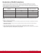
Declaration of RoHS Compliance 7KLV SURGXFW KDV EHHQ GHVLJQHG DQG PDQXIDFWXUHG LQ FRPSOLDQFH ZLWK 'LUHFWLYH (& RI WKH (XURSHDQ 3DUOLDPHQW DQG WKH &RXQFLO RQ UHVWULFWLRQ RI WKH XVH RI FHUWDLQ KD]DUGRXV VXEVWDQFHV LQ HOHFWULFDO DQG HOHFWURQLF HTXLSPHQW 5R+6 'LUHFWLYH DQG LV GHHPHG WR FRPSO\ ZLWK WKH PD[LPXP FRQFHQWUDWLRQ YDOXHV LVVXHG E\ WKH (XURSHDQ Technical Adaptation Committee (TAC) as shown below: Substance Proposed Maximum Concentration Actual Concentration /HDG 3E Mercu
Copyright Information Copyright © ViewSonic® &RUSRUDWLRQ $OO ULJKWV UHVHUYHG Macintosh and Power Macintosh are registered trademarks of Apple Inc. Microsoft, Windows, Windows NT, and the Windows logo are registered trademarks of Microsoft Corporation in the United States and other countries. ViewSonic, the three birds logo, OnView, ViewMatch, and ViewMeter are registered trademarks of ViewSonic Corporation. VESA is a registered trademark of the Video Electronics Standards Association.
User Guide Network Set-up and Operation PJ Network Manager for Windows
User Guide
Features and Design This Multimedia Projector is designed with the most advanced technology for portability, durability, and ease of use. 7KLV SURMHFWRU XWLOL]HV EXLOW LQ PXOWLPHGLD IHDWXUHV D SDOHWWH RI PLOOLRQ FRORUV DQG PDWUL[ OLTXLG FU\VWDO GLVSOD\ /&' WHFKQRORJ\ Ƈ Compact Design Ƈ 7KLV SURMHFWRU LV GHVLJQHG FRPSDFW LQ VL]H DQG ZHLJKW It is easy to carry and installed anywhere you wish to use.
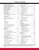
Table of Contents Remote Control Operation Compliance Information . . . . . . . . . . . . . . . . i Important Safety Instructions . . . . . . . . . . . .ii Declaration of RoHS Compliance . . . . . . . . iii Copyright Information . . . . . . . . . . . . . . . . . iv Product Registration . . . . . . . . . . . . . . . . . . iv Features and Design . . . . . . . . . . . . . . . . . . .2 Table of Contents . . . . . . . . . . . . . . . . . . . . . .3 To the Owner. . . . . . . . . . . . . . . . . . . . . . . . . .
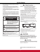
To the Owner Before installing and operating this projector, read this manual thoroughly. This projector provides many convenient features and functions. Operating the projector properly enables you to manage those features and maintains it in good condition for many years to come. Improper operation may result in not only shortening the SURGXFW OLIH EXW DOVR PDOIXQFWLRQV ILUH KD]DUG RU RWKHU accidents.
Safety Instructions All the safety and operating instructions should be read before the product is operated. Do not install the projector near the ventilation duct of DLU FRQGLWLRQLQJ HTXLSPHQW Read all of the instructions given here and retain them for later use. Unplug this projector from AC power supply before cleaning. Do not use liquid or aerosol cleaners. Use a damp cloth for cleaning. This projector should be operated only from the type of power source indicated on the marking label.
Safety Instructions Air Circulation Installing the Projector in Proper Position Openings in the cabinet are provided for ventilation. To ensure reliable operation of the product and to protect it from overheating, these openings must not be blocked or covered. Install the projector properly. Improper installation may UHGXFH WKH ODPS OLIH DQG FDXVH D ILUH KD]DUG 'R QRW UROO WKH SURMHFWRU PRUH WKDQ degrees from side to side.
Compliance AC Power Cord Requirement The AC Power Cord supplied with this projector meets the requirement for use in the country you purchased it. AC Power Cord for the United States and Canada: AC Power Cord used in the United States and Canada is listed by the Underwriters /DERUDWRULHV 8/ DQG FHUWLILHG E\ WKH &DQDGLDQ 6WDQGDUG $VVRFLDWLRQ &6$ $& 3RZHU &RUG KDV D JURXQGLQJ W\SH $& OLQH SOXJ 7KLV LV D VDIHW\ IHDWXUH WR EH VXUH WKDW WKH plug will fit into the power outlet.
Part Names and Functions ① Top controls and Indicators ② Zoom Ring ③ Focus Ring ④ Speaker ⑤ Infrared Remote Receiver ⑥ Projection Lens ⑦ Lens Cap 6HH SDJH IRU DWWDFKLQJ Front ① ② ③ CAUTION Do not turn on a projector with lens cap attached.
Part Names and Functions Rear Terminal ① ② ③ ⑤ ⑦ ⑧ ⑥ ④ ① CONTROL PORT When the projector is controlled by a computer, connect to this jack with serial control cable. ⑤ VIDEO IN Connect the composite video output signal to this jack (p.15).
Part Names and Functions Top Control ⑤ ⑧ ④ ⑦ ③ ② ① ⑥ ① SELECT button ± ([HFXWH WKH VHOHFWHG LWHP S ± ([SDQG RU FRPSUHVV WKH LPDJH LQ WKH 'LJLWDO ]RRP PRGH S ⑤ ② POINT ŸźŻŹ (VOLUME –/+) buttons ± 6HOHFW DQ LWHP RU DGMXVW WKH YDOXH LQ WKH 2Q 6FUHHQ 0HQX S ± 3DQ WKH LPDJH LQ WKH 'LJLWDO ]RRP PRGH S ± $GMXVW WKH YROXPH OHYHO 3RLQW ŻŹbuttons) S POWER indicator ± /LJKWV UHG ZKHQ WKH SURMHFWRU LV LQ VWDQG E\ PRGH ± /LJKWV JUHHQ GXULQJ RSHUDWLRQV ± %
Part Names and Functions Remote Control ① ON/STAND-BY button 7XUQ WKH SURMHFWRU RQ RU RII SS ② AUTO SET button ([HFXWH WKH VHWWLQJ RI $XWR VHWXS LQFOXGHV ,QSXW VHDUFK $XWR 3& DGM and Auto Keystone functions) in the setting menu. SS ③ COMPUTER 1/2 buttons Select the COMPUTER 1 or COMPUTER 2 input source.
Part Names and Functions Remote Control Battery Installation 1 Open the battery compartment lid. 2 Install new batteries into the compartment. 3 Replace the compartment lid. Two AAA size batteries For correct polarity DQG ± EH VXUH battery terminals are in contact with pins in compartment. To ensure safe operation, please observe the following precautions : Ɣ 8VH WZR $$$ RU /5 W\SH DONDOLQH EDWWHULHV Ɣ Always replace batteries in sets. Ɣ Do not use a new battery with a used battery.
Installation Setting up Install the projector according to the environment and manner the projector will be used in. For the case of installation in a special state such as ceiling mount, the specified mounting accessories and service may be required. Before installing the projector, consult your dealer about your installation. Arrangement Refer to the following tables T-1 to determine the screen size and projection distance. The values shown in the table are calculated for a full size screen.
Installation Connecting to a Computer Cables used for connection 9*$ &DEOHV 0LQL ' VXE SLQ 2QO\ RQH FDEOH LV VXSSOLHG $XGLR &DEOHV ( 2QH FDEOH LV VXSSOLHG RWKHU cables are not supplied with the projector.) Audio Output Monitor Output Monitor Input or Monitor Output ([WHUQDO $XGLR (TXLSPHQW VGA cable VGA cable Audio cable (stereo) Audio Input COMPUTER IN 1 6 9,'(2 ,1 /COMPONENT IN COMPUTER IN 2 / MONITOR OUT This terminal is switchable.
Installation Connecting to Video Equipment Cables used for connection 9LGHR &DEOH 6 9LGHR &DEOH 6 9LGHR 9*$ &DEOH $XGLR &DEOHV (Cables are not supplied with the projector.
Installation Connecting to Component Video and RGB (Scart) Equipment Cables used for connection $XGLR &DEOHV 6FDUW 9*$ &DEOH &RPSRQHQW &DEOH &RPSRQHQW 9*$ &DEOH (Cables are not supplied with this projector.
Installation Using the Ferrite Core Before using the AC Power Cord, attach the ferrite core (supplied) as shown below. (See below for mounting location.) The Power Cord with ferrite core must be used for RF interference suppression. PP Ferrite Core AC Power Cord Keep closing until it makes a clicking sound. Connecting the AC Power Cord 7KLV SURMHFWRU XVHV QRPLQDO LQSXW YROWDJHV RI 9 $& and it automatically selects the correct input voltage.
Basic Operation Turning On the Projector 1 Complete peripheral connections (with a computer, VCR, etc.) before turning on the projector. 2 Connect the projector’s AC power cord into an AC outlet. The POWER indicator lights red. Open the lens FDS VHH SDJHV 3 3UHVV WKH 21 67$1' %< EXWWRQ RQ WKH WRS FRQWURO RU on the remote control. The POWER indicator lights green and the cooling fans start to operate. The preparation display appears on the screen.
Basic Operation Enter a PIN code Use the Point Ÿź buttons to enter a number. Press the Point Ż Ź EXWWRQV WR IL[ WKH QXPEHU DQG PRYH WKH UHG IUDPH SRLQWHU WR WKH QH[W ER[ 7KH QXPEHU FKDQJHV WR ³¼”. ,I \RX IL[HG DQ LQFRUUHFW QXPEHU XVH WKH 3RLQW Ż Ź buttons to move the pointer to the number you want to correct, and then enter the correct number. 5HSHDW WKLV VWHS WR FRPSOHWH HQWHULQJ D IRXU GLJLW QXPEHU $IWHU HQWHULQJ WKH IRXU GLJLW QXPEHU PRYH WKH SRLQWHU WR Set.
Basic Operation Turning Off the Projector 1 3UHVV WKH 21 67$1' %< EXWWRQ RQ WKH WRS FRQWURO RU on the remote control, and Power off? appears on the screen. 2 3UHVV WKH 21 67$1' %< EXWWRQ DJDLQ WR WXUQ RII WKH projector. The POWER indicator lights red and the cooling fans stop (default setting), and you can unplug the AC power cord.
Basic Operation How to Operate the On-Screen Menu 7KH SURMHFWRU FDQ EH DGMXVWHG RU VHW YLD WKH 2Q 6FUHHQ Menu. The menus have a hierarchical structure, with a main menu that is divided into submenus, which are further divided into other submenus. For each adjustment and setting procedure, refer to respective sections in this manual. 1 Press the MENU button on the top control or the UHPRWH FRQWURO WR GLVSOD\ WKH 2Q 6FUHHQ 0HQX 2 Use the Point Ÿź buttons to highlight or select a main menu item.
Basic Operation Menu Bar )RU GHWDLOHG IXQFWLRQV RI HDFK PHQX VHH ³0HQX 7UHH´ RQ SDJHV 6XE 0HQX Main Menu ► ① ② Computer 1 RGB Computer 2 RGB Video ③ ④ ⑤ ⑥ ⑦ ⑧ Network ⑨ ˉˉˉ ⑩ ① Input Used to select an input source from Computer 1, Computer 2 or Video SS ② PC adjust Select Auto PC adj.
Basic Operation Zoom and Focus Adjustment 5RWDWH WKH =RRP 5LQJ WR ]RRP LQ DQG RXW Rotate the Focus Ring to adjust the focus of the image. Zoom Ring Focus Ring Auto Setup Function $XWR VHWXS IXQFWLRQ LV SURYLGHG WR DXWRPDWLFDOO\ H[HFXWH WKH setting of Auto setup (includes Input search, Auto PC adj.
Basic Operation Sound Adjustment Top Control Direct Operation Volume VOLUME+/buttons 3UHVV WKH 92/80( ± EXWWRQV RQ WKH WRS FRQWURO RU RQ WKH UHPRWH FRQWURO WR DGMXVW WKH YROXPH 7KH YROXPH GLDORJ ER[ appears on the screen for a few seconds. Remote Control Mute Press the MUTE button on the remote control to select On to temporarily turn off the sound.
Basic Operation Remote Control Operation Using the remote control for some frequently used operations is advisable.
Basic Operation NO SHOW button Press the NO SHOW button on the remote control to black out the image. To restore to normal, press the NO SHOW button again or press any other button. When the projected image is FDSWXUHG DQG LV VHW DV 8VHU LQ WKH /RJR VHOHFWLRQ S WKH screen changes each time you press the NO SHOW button as follows.
Computer Input Input Source Selection (RGB: Computer 1/Computer 2) Direct Operation Choose either Computer 1(RGB) or Computer 2(RGB) by pressing the COMPUTER 1 or COMPUTER 2 button on the remote control. Before using these buttons, correct input source should be selected through Menu operation as described below. Remote Control COMPUTER 1 button Computer 1(RGB) Computer 1(Scart) COMPUTER 2 button Computer 2 (RGB) Input Menu Menu Operation 1 3UHVV WKH 0(18 EXWWRQ WR GLVSOD\ WKH 2Q 6FUHHQ Menu.
Computer Input Computer System Selection 7KLV SURMHFWRU DXWRPDWLFDOO\ WXQHV WR YDULRXV W\SHV RI FRPSXWHUV ZLWK LWV 0XOWL VFDQ V\VWHP DQG $XWR 3& Adjustment. If a computer is selected as a signal source, this projector automatically detects the signal format and tunes to project a proper image without any additional settings.
Computer Input Auto PC Adjustment Auto PC Adjustment function is provided to automatically adjust Fine sync, Total dots, Horizontal and Vertical positions to conform to your computer. PC adjust Menu Menu Operation Auto PC adj. 1 2 3UHVV WKH 0(18 EXWWRQ WR GLVSOD\ WKH 2Q 6FUHHQ Menu. Use the Point Ÿź buttons to select PC adjust and then press the Point Ź RU WKH 6(/(&7 EXWWRQ ► Use the Point Ÿź buttons to select Auto PC adj.
Computer Input Manual PC Adjustment 6RPH FRPSXWHUV HPSOR\ VSHFLDO VLJQDO IRUPDWV ZKLFK PD\ QRW EH WXQHG E\ 0XOWL VFDQ V\VWHP RI WKLV SURMHFWRU Manual PC Adjustment enables you to precisely adjust several parameters to match those signal formats. The SURMHFWRU KDV LQGHSHQGHQW PHPRU\ DUHDV WR VWRUH WKRVH SDUDPHWHUV PDQXDOO\ DGMXVWHG ,W DOORZV \RX WR UHFDOO the setting for a specific computer. 1 2 3UHVV WKH 0(18 EXWWRQ WR GLVSOD\ WKH 2Q 6FUHHQ Menu.
Computer Input Reset Mode free ► To reset the adjusted data, select Reset and press the 6(/(&7 EXWWRQ $ FRQILUPDWLRQ ER[ DSSHDUV DQG WKHQ VHOHFW Yes. All adjustments will return to their previous figures. Mode free To clear the stored data, select Mode free and then press the Point Ź RU WKH 6(/(&7 EXWWRQ 0RYH WKH KLJKOLJKW WR WKH 0RGH WKDW \RX ZDQW WR FOHDU DQG WKHQ SUHVV WKH 6(/(&7 button. Auto PC adj.
Computer Input Image Mode Selection Direct Operation Remote Control Select the desired image mode among Dynamic, Standard, Real, Blackboard (Green), Colorboard, Image 1, Image 2, Image 3 and Image 4 by pressing the IMAGE button on the remote control.
Computer Input Image Adjustment 1 3UHVV WKH 0(18 EXWWRQ WR GLVSOD\ WKH 2Q 6FUHHQ Menu. Use the Point Ÿź buttons to select Image adjust and then press the Point ŹRU WKH 6(/(&7 button. 2 Use the Point Ÿź buttons select the desired item DQG WKHQ SUHVV WKH 6(/(&7 EXWWRQ WR GLVSOD\ WKH DGMXVWPHQW GLDORJ ER[ 8VH WKH 3RLQW ŻŹ buttons to adjust the setting value.
Computer Input Where to store? Store ► To store the adjusted data, select Store and press the Point ŹRU WKH 6(/(&7 EXWWRQ 8VH WKH 3RLQW Ÿź buttons to select one from Image 1 to 4 DQG SUHVV WKH 6(/(&7 EXWWRQ $ FRQILUPDWLRQ ER[ DSSHDUV DQG WKHQ VHOHFW Yes.
Computer Input Custom adj. Adjust the screen scale and position manually with this function. Press the Point Źbutton at Custom adj. and the Custom adjustment menu is displayed on the screen, you can use the Point Ÿź buttons to choose the item you want to adjust. ► Scale H/V .......... $GMXVW WKH +RUL]RQWDO 9HUWLFDO VFUHHQ scale. H&V ................... When set to On, the aspect ratio is IL[HG 7KH Scale V appears dimmed and becomes unavailable.
Video Input Input Source Selection (Video, S-video) Direct Operation Choose Video or S-video E\ SUHVVLQJ WKH 9,'(2 RU WKH 6 VIDEO button on the remote control. Before using these buttons, correct input source should be selected through menu operation as described below. Remote Control VIDEO button Video S-VIDEO button S-video Menu Operation 1 3UHVV WKH 0(18 EXWWRQ WR GLVSOD\ WKH 2Q 6FUHHQ Menu.
Video Input Input Source Selection (Component, RGB Scart 21-pin) Direct Operation Choose Computer 1(Component) or Computer 1(Scart) by pressing the COMPONENT or the COMPUTER 1 button on the remote control. Before using these buttons, correct input source should be selected through Menu operation as described below. Remote Control COMPUTER 1 button Computer 1(RGB) Computer 1(Scart) COMPONENT button Computer 1(Component) Input Menu Menu Operation 1 3UHVV WKH 0(18 EXWWRQ WR GLVSOD\ WKH 2Q 6FUHHQ Menu.
Video Input Video System Selection 1 3UHVV WKH 0(18 EXWWRQ WR GLVSOD\ WKH 2Q 6FUHHQ Menu.
Video Input Image Mode Selection Remote Control Direct Operation IMAGE button Dynamic Select the desired image mode among Dynamic, Standard, Cinema, Blackboard (Green), Colorboard, Image 1, Image 2, Image 3 and Image 4 by pressing the IMAGE button on the remote control.
Video Input Image Adjustment 1 3UHVV WKH 0(18 EXWWRQ WR GLVSOD\ WKH 2Q 6FUHHQ Menu. Use the Point Ÿź buttons to select Image adjust and then press the Point Ź or the 6(/(&7 button. 2 Use the Point Ÿź buttons select the desired item DQG WKHQ SUHVV WKH 6(/(&7 EXWWRQ WR GLVSOD\ WKH DGMXVWPHQW GLDORJ ER[ 8VH WKH 3RLQW ŻŹ buttons to adjust the setting value.
Video Input Sharpness Press the Point Ż button to decrease the sharpness of the image; press the Point Ź button to increase the sharpness RI WKH LPDJH IURP WR Gamma Use the Point ŻŹ buttons to adjust the gamma value to REWDLQ D EHWWHU EDODQFH RI FRQWUDVW IURP WR Noise reduction Noise interference on the screen can be reduced. Select one of the following options to get smoother images. Off ......... Disabled. L1 .......... /RZHU UHGXFWLRQ L2 ..........
Video Input Screen Size Adjustment 7KLV SURMHFWRU KDV WKH SLFWXUH VFUHHQ UHVL]H IXQFWLRQ ZKLFK HQDEOHV \RX WR FXVWRPL]H WKH LPDJH VL]H 1 3UHVV WKH 0(18 EXWWRQ WR GLVSOD\ WKH 2Q 6FUHHQ Menu. Use the Point Ÿź buttons to select Screen and then press the Point Ź RU WKH 6(/(&7 EXWWRQ 2 Use the Point Ÿź buttons select the desired item and WKHQ SUHVV WKH 6(/(&7 EXWWRQ Screen Menu ► ► Normal 3URYLGH WKH LPDJH WR ILW WKH VFUHHQ VL]H ZKLOH PDLQWDLQLQJ the aspect ratio of the input signal.
Setting Setting This projector has a Setting menu that allows you to set up the other various functions described below. 1 3UHVV WKH 0(18 EXWWRQ WR GLVSOD\ WKH 2Q 6FUHHQ Menu. Press the Point Ÿź buttons to select Setting and press the Point Ź RU WKH 6(/(&7 EXWWRQ WR DFFHVV the submenu items. 2 Use the Point Ÿź buttons to select the desired item and then press the Point Ź RU WKH 6(/(&7 EXWWRQ WR access the selected item.
Setting Auto setup Auto setup English This function enables Input search, Auto Keystone correction and Auto PC adjustment by pressing the AUTO SETUP button on the top control or the AUTO SET button on the remote control. Settings for those functions can be altered as follows: Input search This function detects the input signal automatically. When a signal is found, the search will stop. Use the Point Ÿź buttons to select one of the following options. Off ........... Input search does not work. On1......
Setting Keystone Keystone English Blue On Off Computer 2 Direct on Standby mode Off Off Network 1/2 Background Keystone Store Select the background screen for when no input signal is detected. Press the Point Ÿź buttons to switch between each option. Display 7KLV IXQFWLRQ GHFLGHV ZKHWKHU WR GLVSOD\ 2Q 6FUHHQ 'LVSOD\V On ........................... 6KRZ DOO WKH 2Q 6FUHHQ GLVSOD\V Use this function when you want to project images after the lamp becomes bright enough.
Setting Logo (Logo and Logo PIN code lock settings) 3Note: When On LV VHOHFWHG LQ WKH /RJR 3,1 FRGH ORFN IXQFWLRQ Logo select and Capture functions cannot be selected. Logo select English Store Blue On ► Off Off Computer 2 ► 7KLV IXQFWLRQ DOORZV \RX WR FXVWRPL]H WKH VFUHHQ ORJR ZLWK Logo select, capture, Logo PIN code lock and Logo PIN code change functions. Direct on Standby mode Off Off Network 1/2 Logo select 7KLV IXQFWLRQ GHFLGHV RQ WKH VWDUWLQJ XS GLVSOD\ IURP among following options.
Setting Capture This function enables you to capture an image being SURMHFWHG WR XVH LW IRU D VWDUWLQJ XS GLVSOD\ RU LQWHUYDO RI presentations. Capture Off Off Select Capture DQG SUHVV WKH 6(/(&7 EXWWRQ $ FRQILUPDWLRQ ER[ DSSHDUV DQG VHOHFW Yes to capture the projected image. ► $IWHU FDSWXULQJ WKH SURMHFWHG LPDJH JR WR WKH /RJR VHOHFW function and set it to User.
Setting Enter a Logo PIN code Use the Point Ÿź buttons to enter a number. Press the Point ŻŹ EXWWRQV WR IL[ WKH QXPEHU DQG PRYH WKH UHG IUDPH SRLQWHU WR WKH QH[W ER[ 7KH QXPEHU FKDQJHV WR ¼ ,I \RX IL[HG DQ LQFRUUHFW QXPEHU XVH WKH 3RLQW ŻŹ buttons to move the pointer to the number you want to correct, and then enter the correct number.
Setting Ceiling Ceiling When this function is set to On, the picture will be top/ bottom and left/right reversed. This function is used to SURMHFW WKH LPDJH IURP D FHLOLQJ PRXQWHG SURMHFWRU Rear When this function is set to On, the picture will be left/right reversed. This function is used to project the image from rear of the screen.
Setting Power management Power management For reducing power consumption as well as maintaining the lamp life, the Power management function turns off the projection lamp when the projector is not operated for a certain period. 7LPH OHIW EHIRUH /DPS LV RII English Blue On Off Off Computer 2 ► Select one of the following options: Ready ............... When the lamp has been fully cooled down, the POWER indicator changes to green blinking.
Setting Standby mode This function is available when operating the projector via network. Network .... Supply the power to the network function even after turning off the projector by pressing the 21 67$1' %< EXWWRQ RQ WKH UHPRWH FRQWURO You can turn on/off the projector via network, modify network environment, and receive DQ H PDLO DERXW SURMHFWRU VWDWXV ZKLOH WKH projector is powered off. Eco ............ Select Eco when you do not use the projector via network.
Setting Closed Caption Closed Caption Closed Caption is a printed version of the program sound or other information displayed on the screen. If the input signal contains closed captions, you can turn on the feature and switch the channels. Press the Point Ÿź buttons to select Off, CC1, CC2, CC3 or CC4. II WKH FORVHG FDSWLRQ LV QRW FOHDU \RX FDQ FKDQJH WKH WH[W from Color to White. Closed caption 3Note: Off Color ► The Closed Caption is available only under the situation below.
Setting Lamp control Lamp control This function allows you to change brightness of the screen. High ........... Brighter than the Normal mode. Normal ....... Normal brightness Eco ............ /RZHU EULJKWQHVV UHGXFHV WKH ODPS SRZHU FRQVXPSWLRQ DQG H[WHQGV WKH lamp life. 3Note: /DPS PRGH FDQQRW EH FKDQJHG IRU D ZKLOH DIWHU WXUQLQJ RQ WKH SURMHFWRU /DPS QHHGV VRPH WLPH WR VWDELOL]H after the power is turned on.
Setting Key lock Security (Key lock and PIN code lock) This function allows you to use the Key lock and PIN code lock function to set the security for the projector operation. Key lock This function locks the top control and remote control EXWWRQV WR SUHYHQW RSHUDWLRQ E\ XQDXWKRUL]HG SHUVRQV Select Key lock DQG WKHQ SUHVV WKH 6(/(&7 EXWWRQ and select the desired item by pressing the Point Ÿź buttons. ..... Unlocked. ..... /RFN WKH RSHUDWLRQ RI WKH WRS FRQWURO 7R unlock, use the remote control. ....
Setting Enter a PIN code Use the Point Ÿź buttons to enter a number. Press the Point Ż Ź EXWWRQV WR IL[ WKH QXPEHU DQG PRYH WKH UHG IUDPH SRLQWHU WR WKH QH[W ER[ 7KH QXPEHU FKDQJHV WR ¼ ,I \RX IL[HG DQ LQFRUUHFW QXPEHU XVH WKH 3RLQW Ż Ź buttons to move the pointer to the number you want to correct, and then enter the correct number. Enter a PIN code 5HSHDW WKLV VWHS WR FRPSOHWH HQWHULQJ D IRXU GLJLW number.
Setting Fan This function provides the following options in the cooling IDQV¶ RSHUDWLRQ ZKHQ WKH SURMHFWRU LV WXUQHG RII S L1 ...... 7KH FRROLQJ IDQV URWDWH IRU DERXW VHFRQGV L2 ...... The cooling fans stop. 3Note: When L2 is selected in Fan menu and the projector is turned on right after it turns off, it takes a while to start projecting. Fan control Choose the running speed of cooling fans from the following options according to the ground elevation under which you use the projector. Off.....
Setting Filter counter Filter counter This function is used to set a frequency for the filter cleaning. When the projector reached a specified time for cleanings, a Filter warning icon appears on the screen, notifying the cleaning is necessary. After cleaning the filter, be sure to select Reset and set the timer. The Filter warning icon will not turn off until the filter counter is reset. For details about resetting the timer, refer to “Resetting the )LOWHU &RXQWHU´ RQ SDJH Fig.
Information Input Source Information Display The Information Menu is used for checking the status of the image signal being projected and the operation of the projector. Direct Operation Press the INFO. button on the remote control to display the Information Menu. Remote Control INFO. button Menu Operation Press the Point Ÿź buttons to select the Information. The Information Menu is displayed. See below for displayed information. Input The selected input source is displayed.
Maintenance and Cleaning WARNING indicator The WARNING indicator shows the state of the function which protects the projector. Check the state of the WARNING indicator and the POWER indicator to take proper maintenance. The projector is shut down and the WARNING indicator is blinking red. Top Control When the temperature inside the projector reaches a certain level, the projector will be automatically shut down to protect the inside of the projector.
Maintenance and Cleaning Cleaning the Filters Filter prevents dust from accumulating on the optical elements inside the projector. Should the filters become clogged with dust particles, it will reduce cooling fans’ effectiveness and may result in internal heat buildup and adversely affect the life of the projector. If a “Filter warning” icon appears on the screen, clean the filters immediately. Clean the filters by following the steps below.
Maintenance and Cleaning Attaching the Lens Cap When moving this projector or while not using it over an H[WHQGHG SHULRG RI WLPH UHSODFH WKH OHQV FDS Attach the lens cap according to the following procedures. 1 Thread the string through the hole on the lens cap and then tie a knot in the string to secure it in place. 2 To pass the other end of the string into the hole on the bottom of the projector and pull at it. Cleaning the Projection Lens Unplug the AC power cord before cleaning.
Maintenance and Cleaning Lamp Replacement When the projection lamp of the projector reaches its end RI OLIH WKH /DPS UHSODFHPHQW LFRQ DSSHDUV RQ WKH VFUHHQ DQG /$03 5(3/$&( LQGLFDWRU OLJKWV \HOORZ 5HSODFH WKH ODPS ZLWK D QHZ RQH SURPSWO\ 7KH WLPLQJ ZKHQ WKH /$03 5(3/$&( LQGLFDWRU VKRXOG OLJKW LV GHSHQGLQJ RQ WKH ODPS mode. Top Control LAMP REPLACE indicator Lamp replacement icon 3Note: 7KH /DPS UHSODFHPHQW LFRQ ZLOO QRW DSSHDU ZKHQ WKH 'LVSOD\ IXQFWLRQ LV VHW WR Off S GXULQJ Freeze (p.
Maintenance and Cleaning ORDER REPLACEMENT LAMP Replacement lamp can be ordered through your dealer. When ordering a projection lamp, give the following information to the dealer. Model No. of your projector Ɣ Replacement Lamp Type No.
Appendix Troubleshooting Before calling your dealer or service center for assistance, check the items below once again.
Appendix No image No sound The color is strange. Some displays are not seen during the operation. ± &KHFN WKH FRQQHFWLRQ EHWZHHQ \RXU FRPSXWHU RU YLGHR HTXLSPHQW DQG WKH SURMHFWRU 6HH SDJHV ± 6HH LI WKH LQSXW VLJQDO LV FRUUHFWO\ RXWSXW IURP \RXU FRPSXWHU 6RPH laptop computers may need to change the setting for monitor output when connecting to a projector. See your computer’s instruction manual for the setting.
Appendix The image is distorted or runs off. ± &KHFN PC adjust menu or Screen menu and adjust them. 6HH SDJHV PIN code dialog box appears at start-up. ± 3,1 FRGH ORFN LV EHLQJ VHW (QWHU D 3,1 FRGH WKH ³ ´ RU QXPEHUV \RX KDYH VHW 6HH SDJHV The Remote Control does not work. ± &KHFN WKH EDWWHULHV ± 0DNH VXUH QR REVWUXFWLRQ LV EHWZHHQ WKH SURMHFWRU DQG UHPRWH control.
Appendix Menu Tree Computer Input/Video Input Input Input RGB Computer 1 Component RGB (Scart) 6 YLGHR RGB Computer 2 Video Sound ± On/Off Volume Mute Sound Computer Input Image select Dynamic Standard Real Blackboard (Green) Red/Blue/Yellow/Green Colorboard Image 1 Image 2 ,PDJH ,PDJH Image Adjust Contrast Brightness Color temp. SVGA 1 Mode 1 Mode 2 System (1) 6\VWHPV GLVSOD\HG LQ WKH 6\VWHP 0HQX YDU\ depending on an input signal. PC adjust Auto PC adj.
Appendix Video Input Setting System Image select Setting Auto L L S S S L L System (2) ODQJXDJHV SURYLGHG Menu position Auto 3$/ SECAM NTSC 176& 3$/ 0 3$/ 1 /DQJXDJH Auto setup Input search Keystone Auto PC adj.
Appendix Indicators and Projector Condition Check the indicators for projector condition. Indicators POWER WARNING red/green red Projector Condition /$03 5(3/$&( yellow The projector is off. (The AC power cord is unplugged.) ¼ 7KH SURMHFWRU LV LQ VWDQG E\ PRGH 3UHVV WKH 21 67$1' %< EXWWRQ to turn on the projector. ¼ The projector is operating normally. ¼ 7KH SURMHFWRU LV SUHSDULQJ IRU VWDQG E\ RU WKH SURMHFWLRQ ODPS LV being cooled down.
Appendix Compatible Computer Specifications %DVLFDOO\ WKLV SURMHFWRU FDQ DFFHSW WKH VLJQDO IURP DOO FRPSXWHUV ZLWK WKH 9 + )UHTXHQF\ PHQWLRQHG EHORZ DQG OHVV WKDQ 0+] RI 'RW &ORFN When selecting these modes, PC adjustment can be limited.
Appendix Technical Specifications Mechanical Information 'LPHQVLRQV : [ + [ ' 1HW :HLJKW )RRW $GMXVWPHQW [ [ PP [ PP [ PP (Not including protrusions) OEV NJ Û WR Û Panel Resolution /&' 3DQHO 6\VWHP 3DQHO 5HVROXWLRQ 1XPEHU RI 3L[HOV 7)7 $FWLYH 0DWUL[ W\SH SDQHOV [ GRWV [ [ SDQHOV Signal Compatibility Color System 6' +' 79 6LJQDO 6FDQQLQJ )UHTXHQF\ 3$/ 6(
Appendix PJ Link Notice 7KLV SURMHFWRU LV FRPSOLDQW ZLWK 3-/LQN 6WDQGDUG &ODVV RI -%0,$ -DSDQ %XVLQHVV 0DFKLQH DQG ,QIRUPDWLRQ 6\VWHP ,QGXVWULHV $VVRFLDWLRQ 7KLV SURMHFWRU VXSSRUWV DOO FRPPDQGV GHILQHG E\ 3-/LQN &ODVV DQG LV YHULILHG FRQIRUPDQFH ZLWK 3-/LQN 6WDQGDUG &ODVV )RU 3- /LQN SDVVZRUG VHH WKH 8VHU *XLGH RI ³1HWZRUN 6HW XS DQG 2SHUDWLRQ ´ 3-/LQN ,QSXW Projector Input Computer 1 Parameter RGB RGB 2 12 Component 5*% RGB (Scart) RGB 5 15 6 YLGHR 5*% Computer 2 RGB
Appendix Configurations of Terminals COMPUTER IN 1 / S-VIDEO IN/ COMPONENT IN Terminal: Analog RGB (Mini D-sub 15 pin) 4 5 10 15 2 3 9 14 8 1 7 12 13 6 11 1 2 3 4 5 6 7 8 5HG &U 6 & ,QSXW *UHHQ < 6 < ,QSXW %OXH &E ,QSXW *URXQG +RUL] V\QF Ground (Red) Ground (Green) Ground (Blue) 9 10 11 12 13 14 15 9 3RZHU Ground (Vert.sync.) Ground 9 10 11 12 13 14 15 Ground (Vert.sync.) +RUL] V\QF ,QSXW 2XWSXW Vert. sync.
Appendix Dimensions Unit: mm(inch) Screw Holes for Ceiling Mount 6FUHZ 0 'HSWK 86.5(3.41) 250.5(9.86) 141.5(5.57) 205.0(8.07) 217.0(8.54) 205.0(8.07) 86.5(3.41) 90.0(3.54) 109.0(4.30) 54.2(2.13) 37.3(1.47) 89.3(3.51) 241.4(9.50) 178.7(7.04) 57.6(2.27) 105.9(4.17) 93.3(3.67) 41.9(1.65) 48.7(1.92) 48.1(1.89) 32.9(1.30) 133.8(5.27) 15.5 (0.61) 118.0(4.65) 35.9(1.41) 333.5(13.13) 96.5(3.80) 99.5(3.92) 19.0(0.75) 80.5(3.17) 17.1 12.0 (0.67) (0.47) 340.5(13.41) 50.
Appendix Serial Control Interface 7KLV SURMHFWRU SURYLGHV D IXQFWLRQ WR FRQWURO DQG PRQLWRU WKH SURMHFWRU¶V RSHUDWLRQV E\ XVLQJ WKH 56 & VHULDO port. Operation 1 &RQQHFW D 56 & VHULDO FURVV FDEOH WR &21752/ PORT on the projector and serial port on the PC. 6HH S 2 /DXQFK D FRPPXQLFDWLRQ VRIWZDUH SURYLGHG ZLWK 3& and setup the communication condition as follows: 3 Type the command for controlling the projector and then enter the “Enter” key.
Appendix Status Read Command Format The command is sent from PC to the projector with the format below; ‘CR’ [Command] ‘CR’ Command: one character (refer to the command table below.
Customer Support For technical support or product service, see the table below or contact your reseller. Note : You will need the product serial number. Country/Region Website Australia/New Zealand www.viewsonic.com.au Canada www.viewsonic.com Europe Hong Kong India www.viewsoniceurope.com www.hk.viewsonic.com www.in.viewsonic.com Ireland (Eire) www.viewsoniceurope.com/uk/ Korea /DWLQ $PHULFD (Argentina) /DWLQ $PHULFD &KLOH /DWLQ $PHULFD (Columbia) /DWLQ $PHULFD 0H[LFR www.kr.viewsonic.
Limited Warranty VIEWSONIC® PROJECTOR What the warranty covers: ViewSonic warrants its products to be free from defects in material and workmanship, under normal use, during the warranty period. If a product proves to be defective in material or workmanship during the warranty period, ViewSonic will, at its sole option, repair or replace the product with a like product. Replacement product or parts may include remanufactured or refurbished parts or components.
How to get service: 1. For information about receiving service under warranty, contact ViewSonic Customer Support (please refer to “Customer Support” page). You will need to provide your product’s serial number. 2. To obtain warranted service, you will be required to provide (a) the original dated sales slip, (b) your name, (c) your address, (d) a description of the problem, and (e) the serial number of the product. 3.
Mexico Limited Warranty VIEWSONIC® PROJECTOR What the warranty covers: ViewSonic warrants its products to be free from defects in material and workmanship, under normal use, during the warranty period. If a product proves to be defective in material or workmanship during the warranty period, ViewSonic will, at its sole option, repair or replace the product with a like product. Replacement product or parts may include remanufactured or refurbished parts or components & accessories.
Contact Information for Sales & Authorized Service (Centro Autorizado de Servicio) within Mexico: Name, address, of manufacturer and importers: 0p[LFR $Y GH OD 3DOPD 3LVR 'HVSDFKR &RUSRUDWLYR ,QWHUSDOPDV &RO 6DQ )HUQDQGR +XL[TXLOXFDQ (VWDGR GH 0p[LFR 7HO KWWS ZZZ YLHZVRQLF FRP OD VRSRUWH LQGH[ KWP NÚMERO GRATIS DE ASISTENCIA TÉCNICA PARA TODO MÉXICO: 001.866.823.
Network Set-up and Operation
2
CAUTION IN USING THE PROJECTOR VIA NETWORKS Ɣ When you find a problem with the projector, remove the power cable immediately and inspect the unit. Using the projector with failure may cause fire or other accidents. Ɣ If you remotely use the projector via networks, carry out a safety check regularly and take particular care to its environment. Incorrect installation may cause fire or other accidents.
Table of contents Safety instructions ...........................................................................................................................................................3 Table of contents ..............................................................................................................................................................4 Chapter 1 Preparation ................................................................................................5 Features..........
Chapter 1 Preparation 1 ENGLISH Describes features and operating environment of this projector.
Chapter 1 Preparation Features Web Management function ( p.31) With this func tion, you can monitor projector functions such as power status, lamp s t at us, inp u t m o d e, signal condition, lamp-use time, etc. through the network by using the web browser installed on your computer. PC1 PC2 PC3 PC4 PJ2 PJ1 PC6 PC5 Turn ON PJ2 E-Mail Alert function ( p.
Features Required operating environment for computers When operating the projector via networks, computers should meet the operating environment below. Operating System Windows 2000, Windows XP (32bit version), Windows Vista (32bit version), Windows 7 (32bit version) Mac OS X v 10.4 or 10.5 Computer environment Recommended CPU Windows: Pentium III 900MHz or more Macintosh : 800 MHz PowerPC G4 or faster, or 1.
Chapter 1 Preparation Cabling Between the Projector and a Hub or computer*1 Use an appropriate cable when connecting the projector and a hub or computer. Connection Ethernet cable type Max. cable length Projector - Hub STP straight-through category 5 * cable 100m (328feet) Projector - Computer STP crossover category 5*2 cable 100m (328feet) 2 *1 There may be other limitations depending on your network environment or LAN specification. Please consult your network administrator for further details.
Flow of installation Flow of installation To use the projector via the networks, follow the setup procedures below. STEP 1 Connect the LAN and set the configuration. Decide depending on the LAN environment. “2. Setup Procedures” (pp.11–16). Detailed LAN configurations need to be done with a browser later. First, complete the Wired LAN connection between computers and projectors, then start browser configurations. STEP 2 “3. Basic setting and operation” (pp.17–30).
Chapter 1 Preparation
Chapter 2 Setup Procedures 2 ENGLISH Describes how to configure the network.
Chapter 2 Setup Procedures Setting procedures and contents differ depending on the LAN installation location. When installing, consult your system administrator to set up the LAN appropriately. Connecting to the LAN line Connect the LAN cable to the LAN connection terminal of the projector. LAN Connection Terminal ACT Lamp (Orange) Blink orange when the projector is sending or receiving the data. LINK Lamp (Green) Light green when the projector is connected to the network correctly.
Network configuration 3. Select "Network setting" in the Network menu and press SELECT button, and then the LAN setting screen will appear and selected LAN settings will be displayed. Adjust each item to the setting environment. Consult your system administrator about the detailed settings. Press SELECT button in a row where you want to adjust, and adjust the figures with the Point ed buttons and move among the items with the Point buttons, and then press SELECT button to fix.
Chapter 2 Setup Procedures Network PIN code The Network PIN code is to restrict the access to the projector through the network. After setting the Network PIN code, you need to enter it to operate the projector via the networks. 1. Select "Network PIN code" in the Network menu, and press SELECT button. The Network PIN code screen will appear. 2. Set the Network PIN code. Set the figures with the Point ed buttons and move to the next items with the Point buttons.
Network factory default Network factory default ENGLISH 1. Select “Network factory default” in the Network menu and press SELECT button. 2. A confirmation box appears and select "Yes" and then press SELECT button. 3. Another confirmation box appears and select "Yes" and then press SELECT button. 4. All the wired LAN settings will go back to the factory default settings. For details, refer to “Wired LAN factory default settings” (p.16).
Chapter 2 Setup Procedures Wired LAN factory default settings SELECTED LAN Parameter LAN 1 LAN 2 LAN 3 DHCP OFF ON OFF IP ADDRESS 169.254.100.100 192.168.100.100 192.168.100.100 SUBNET MASK 255.255.0.0 255.255.255.0 255.255.255.0 GATEWAY ADDRESS 255.255.255.255 255.255.255.255 255.255.255.255 DNS ADDRESS 255.255.255.255 255.255.255.255 255.255.255.
Chapter 3 Basic Setting and Operation 3 ENGLISH Describes basic operations and settings for controlling the projector by using the web browser. It is required that computer and projector is connected to the network and the network address is properly configured.
Chapter 3 Basic Setting and Operation Login the setting page of the projector [1] Enter the IP address Launch the web browser installed in your computer, enter the IP address into the "Address" on the browser and then press "Enter" key. Enter the address that you configured in item "Network configuration" ( p.12). * The numerical value is a setting example. [2] Login If the setting page has set the password, the authentication window will appear.
Login the setting page of the projector [3] Display of main setting page The following main setting page will be displayed according to your display mode selection. Perform various kinds of settings through this page. Click on the menus to display the control and setting pages. Main setting page in the display Sub menu tab Switches the sub menu tab. Setting page Displays the control and setting items according to the selected menu.
Chapter 3 Basic Setting and Operation How to use the setting page To control and set up the projector, use the setting menus on the web browser. Describes the basic operation and procedures commonly used on this manual. Example of the setting page The setting menu appears when clicking the sub menu tab. * Each item has a valid setting range respectively. Types of setting Text box setting Enter a number or text and then click Set button. or Change a value with – or + button.
How to use the setting page Radio button setting Select an item by selecting a radio button. Check box setting ENGLISH Select items by ticking on check boxes.
Chapter 3 Basic Setting and Operation Initial setting After installing the projector, perform the following basic initial setting. Click Initial Setting on the main menu to display the initial setting page. Item Description Language..............Switches display language on the setting page. (Japanese, English) Model name .......Indicates the model name of the projector Network PIN code ......Sets the Network PIN code to login the setting page ( p.23) PJLink.......................
Initial setting Network PIN code setting This is to set the Network PIN code to restrict the access from an unauthorized person through the network. Enter a 4-digit number as the Network PIN code onto the text box and click Set button. The projector begins restarting and it takes about 10 seconds. Close (Quit) the web browser and access to the login page again in 10 seconds. This is to perform the login authentication firmly. The default Network PIN code [0000] means no Network PIN code is set.
Chapter 3 Basic Setting and Operation Network configuration Click Network on the main menu. The following setting page is displayed. The IP Address, Subnet Mask, Default Gateway, DNS (Domain Name Server) and projector name are set up on this menu. The IP address and Subnet Mask have been configured already in chapter "Installation". If you want to change them or configure default gateway or DNS, perform them in this page. If you change them, the projector begins restarting and it takes about 10 seconds.
E-mail setting E-mail setting This projector has an E-mail function which can send an alert message to users or an administrator if it detects an abnormality on the projector or run out of the life span of the lamp. Click E-mail Setting on the main menu and follow the below steps. Item .................................Description SMTP server ...........................Enter server name or IP address of the SMTP server. (up to 60 characters) SMTP server port ...............
Chapter 3 Basic Setting and Operation 1 Setting SMTP server and administrator address Enter the server name or IP address of the SMTP server* 1, the port number of the SMTP server and administrator address and click Set button. The administrator address is set to "Reply-To" address of the message sent from the projector. *1 The SMTP server is a server for sending e-mail. Please contact your network administrator to have this SMTP server address.
E-mail setting 4 Setting POP server When "POP before SMTP" is selected at "Auth" of "SMTP Authentication setting", enter "POP server*2" and "POP server port" and click Set button. *2 The POP server is a server for receiving e-mail. Please contact your network administrator to have this POP server address. Error message for sending alert mail Error message for missing SMTP server When the projector has an abnormality, an alert message will be sent to the registered E-mail address.
Chapter 3 Basic Setting and Operation Examples: Type and contents of alert mail When the projector has an abnormality, the following alert messages are sent to the registered E-mail address according to your selected condition. Administrator or user can take an efficient action quickly by receiving this message. This is very useful to maintain and service the projector. The following are examples of received messages.
SNMP setting SNMP setting This projector provides a SNMP (Simple Network Management Protocol) agent function. The SNMP consists of a manager and agents. The group which communicates information each other with SNMP is called "Community". There are two access modes in a community, Refer (read only) and Set (readwrite). This projector allows to use Refer (read only) only. The SNMP message informs the projector status called "Trap" to an administrator. Click SNMP Setting on the main menu and set up each item.
Chapter 3 Basic Setting and Operation Trap check/delete Check and delete the trap address Checking the registered trap address and deleting the address. To delete the address, tick check box in front of the IP address and click Delete button. Up to 10 trap addresses can be registered. Trap option Trap option setting Tick check boxes in front of the condition item to send the trap. Click Set button if you tick or un-tick the check box on a page.
Chapter 4 Controlling the Projector 4 ENGLISH Describes controlling and setting of the projector by using the web browser.
Chapter 4 Controlling the Projector Power control and status check Click Power & Status on the main menu. The control page will be displayed. By clicking ON or Standby button on the page, the power of the projector can be controlled. Confirmation window as shown in the below appears when the Standby button is pressed. Popup confirmation window Item Description PJ status Power .........................Displays the status of the lamp. (ON, OFF, On starting up, On cooling down) Status ....................
Power control and status check About projector condition Status Description Normal............................................................... Projector is operating normally. Power management in operation........... Power management is operating Lamp failure................................................... Lamp failure is occurring Abnormal Temperature......................... The temperature of the projector became too high Standby after Abnormal Temp......... Projector detects abnormal temp.
Chapter 4 Controlling the Projector Control Click Control on the main menu. The setting method differs depending on the contents of the page. Click on the page number to change pages and select desired setting items. Please see the owner's manual of the projector to have the further information of each control item. Input This function is to select the input mode and source mode of the projector. Click Set button after selecting the input and source mode. Item Description Input.........................
Control System This function is to select the system of signal input to the projector. The available system mode are listed on the pull-down menu button according to the input signal. Select a system and then click Set button. Available selection at the RGB input Item Description XGA1 ........................It automatically switches to the proper computer system of the input signal. * The computer system modes (VGA, SVGA, XGA. SXGA, UXGA, WXGA...) which meet the input signal are listed.
Chapter 4 Controlling the Projector Sound This function is to adjust the sound of the projector. The values in the text box represent the current control value or status. Item Description Volume ...................Adjusts the sound volume from the speaker. (0 ~ 31) Mute.........................Suppresses the sound.
Control Image adjustment This function is to adjust the projected picture image and save the image mode. To store the adjusted value, click Store button, and to load the adjusted value, click Load button. Item Description Contrast .............................. Adjusts picture contrast (0~ 63) Brightness ......................... Adjusts picture brightness (0~ 63) Color...................................... Adjusts picture color saturation (0~ 63) Tint .........................................
Chapter 4 Controlling the Projector PC adjustment Click PC Adj. on the main menu. This function is to adjust the signal from the computer connected to the projector to obtain the proper picture image on the screen. Item Description Current mode......Displays a current mode like VGA, SVGA, XGA. SXGA, UXGA, WXGA, etc. or Mode1 - Mode10 which are the customized mode created by using the "Mode Store" function described below. Auto PC adj..........Performs automatic adjustment. Fine sync ..............
Setting up the projector Setting up the projector Click Setting on the main menu. This function is to set up the projector. Select the sub menu [Screen setting] or [Setting] and then set up each setting. Screen setting This function is to adjust the screen mode of the projector. The values in the text box represent the current screen status. Item Description Screen .....................Switches the screen mode.
Chapter 4 Controlling the Projector Setting 1 Item Description Language..............Sets the language display of projector's on-screen display menu. Auto setup ...........Executes the Auto PC Adj, Input Search and Auto keystone function below according to the each setting after clicking Start button. Auto PC Adj. .....Sets Auto PC Adjustment mode. (ON, OFF) Input search .....Sets the auto-input signal detection mode. (ON1, ON2, OFF) Auto keystone ....Sets Auto Keystone mode.
Setting up the projector Setting 3 Item Description ENGLISH Key lock..................Sets the prohibition of controls either Projector or Remote control. (OFF, Projector keys, Remote control) Fan control ............. Sets the fan control speed. OFF Normal mode ON1 Highland mode 1 ON2 Highland mode 2 Lamp Corres. Value(h)..................Displays the lamp use time (Corresponding value) . Reset the time after lamp replacement.
Chapter 4 Controlling the Projector Information This page is to display the basic information of the projector status. Click Information on the main menu. Click this button to update the information. Items Description Input System Signal Screen Lamp status Security PJ time(h) Lamp Corres. Value(h) Filter time(h) Displays selected input and source. Displays selected signal system. Input signal status (Yes, No) Displays screen mode. Displays lamp status with an icon. Refer to the table as shown below.
Chapter 5 Appendix 5 Connection examples Use of telnet Web browser setting ENGLISH Q&A ViewSonic 3-/ 3-/
Chapter 5 Appendix Examples of connection Peer-To-Peer connection Connecting the projector (PJ01) to the control computer (PC05) directly. * STP cross cable Computer Name: PC05 IP Address : 192.168.0.5 Subnet Mask : 255.255.255.0 Default Gateway : DNS : Projector Name: PJ01 IP Address : 192.168.0.2 Subnet Mask : 255.255.255.0 Default Gateway : 0.0.0.0 DNS : 0.0.0.0 Connecting the projector (PJ01) to the control computer (PC05) via the hub. Hub To another network Computer Name: PC05 IP Address : 192.
Examples of connection The gateway (Router) installed in the network Connecting the projector (PJ01) to the control computer (PC05) via the gateway. Entrance hall Computer Name IP Address Subnet Mask Default Gateway DNS : PC205 : 192.168.200.5 : 255.255.255.0 : 192.168.200.1 : 192.168.201.1 Projector Name: PJ01 IP Address Subnet Mask Default Gateway DNS : 192.168.200.15 : 255.255.255.0 : 192.168.200.1 : 192.168.201.1 Hub Network Group: 192.168.200.
Chapter 5 Appendix Use of telnet You can control the projector by using the telnet application*1 installed on your computer. Normally, the telnet application is available on your computer. * The telnet 10000 port is used to control the projector. Control (For example, in case of using the telnet application of Windows XP Professional.) 1. Select Run... submenu from Start menu on the computer. Type "telnet" onto the Open text area on the displayed window and press OK button.
Use of telnet 3. When communication is established correctly, the word "PASSWORD:" appears on the window. Type the login password (Network PIN code*2) for the projector and then press "Enter" key on the keyboard. If you do not set up the Network PIN code, just press "Enter" key. When the word "Hello" is replied, login has been succeeded. * The password "1234" is used for the example. 4. Type the commands, refer to below table, to control the projector and then press "Enter" key for termination.
Chapter 5 Appendix Web browser setting This projector is designed to be set up and controlled from an Internet web browser. Depending on the preference settings of the web browser, some control functions may not be available. Please make sure that the following functions are set up properly in the web browser. Active Script/JavaScript enable There are some control items used with the JavaScript function in the setting pages.
Web browser setting Examples: OS/Browsers Windows XP Professional Internet Explorer v.6.0 ActiveScript setting ENGLISH Select Internet Options from Tools menu on the web browser and then select Security tab and click Customize Level… button. On the security setting window, scroll down and find the Scripting item, make sure that "Enable" is selected in item Active Scripting.
Chapter 5 Appendix Proxy setting Select Internet Options from Tools menu on the web browser and then select Connection tab and click LAN Settings button. Properly set up your web browser's the proxy server settings according to the local area network environment to which the projector is connected. - Using proxy server To use an external internet connection from the local area network, check the item Use a proxy server and enter the proxy server address and port correctly in the proxy settings window.
Web browser setting Netscape Navigator v.7.1 JavaScript Setting Select Preference from Edit menu on the web browser and then selec t the item Advanced/Scripts & Plugins in the Category column. Make sure that the Enable JavaScript for Navigator is checked. Proxy setting Select Preference from Edit menu on the web browser and then select the item Advanced/ Proxies in the Category column.
Chapter 5 Appendix MAC OS X v 10.4 Safari v.3.2.1 JavaScript enable setting Selec t Preferences... from Safari on the web browser and then select Security tab and check Enable JavaScript. Proxy setting 1 Open Preferences... from Safari menu on the web browser Safari. The preference menu appears. 2 Select Advanced icon and then click Proxies: Change Settings ....
Q&A Q&A Installation/Access Q Why doesn’t the setting page appear in my web browser? A Following causes are possible. Please check them. 1. The projector does not connect to the network. Check LED indicators status ( p.12). - Check the connection of LAN cable if the LINK Lamp does not light green. - Check the network configuration of the projector if the ACT Lamp does not blink orange. 2. Wrong network configuration of the computer. Check the network configuration of the computer. 3.
Chapter 5 Appendix Q We use the DHCP/BOOTP server to assign the IP address. Is it possible to use the projector in this network environment? A Possible. This projector supports the DHCP/BOOTP server. To use this projector in this network environment, set it up so that the DHCP/BOOTP server does not assign the IP address configured to this projector for another device on the network. Please consult your network administrator ( pp.13, 24).
Q&A Operation Q Why can't be turned on/off with web browser? A Please make sure the settings of the projector are correct to use the projector. Please set the Standby mode of the projector's Setting menu to "Network". Refer to "4. Controlling the Projector" "Power control and status check" ( pp.32 - 33). Q Why can't I change the controls in the setting page with web browser? A Please make sure the projector is turned on. If it is in the standby mode, the setting is not effective to the projector.
Chapter 5 Appendix Others Q What are the rules for IP address assignment? A If the network is constructed with TCP/IP protocol, a unique IP address is required for each piece of network equipment. The following are basic rules of the assignment. Rule1 Do not configure the same IP address to the network equipment in the same network group. Each piece of equipment must be assigned a unique IP address. If the IP address is set [192.168.x.x], the Subnet Mask should be set [255.255.255.0] for example.
Q&A Q Can I update the firmware of the projector. It is possible to update the firmware through the network. It is required to have a special tool for the updating. For further information please consult your local dealer. The version number of the firmware is indicated on the lower part of the "Initial setting" page.
PJ Network Manager for Windows
Contents Contents .................................................................................. 2 Chapter 1 Introducing .......................................................... 3 Introducing......................................................................................................................................................3 SNMP ..............................................................................................................................................................
Chapter 1 Introducing Introducing This PJ Network Manager is a SNMP manager software for the network equipment which supports the private MIB (Management Information Base). By installing the PJ Network Manager to the computer, you can monitor the equipment simply such as the projector, the projection monitor and the flat display monitor connected to the network. * The PJ Network Manager can handle our products which has a SNMP agent function.
Chapter 1 Introducing Operating Environment Item Minimum Recommended CPU Pentium III 400MHz or higher Pentium 4 2.0GHz or higher for Windows XP Pentium 4 3.
Chapter 2 Set up ViewSonic 5 5 2 SNMP Manager Software
Chapter 2 Set up PJ Network Manager installation 1 Set the supplied CD-ROM into the CD-ROM drive of your computer. Double click SetupTool. exe icon in the "PJ Network Manager" folder in the CD-ROM. 2 Select "[English [United States]" from the pull- down menu on the "Choose Setup Language" window and click OK button to start installing and then follow the installation wizards.
Chapter 3 Basic Operation ViewSonic 7 7 3 SNMP Manager Software
Chapter 3 Basic Operation Launching and quitting PJ Network Manager To launch PJ Network Manager, take one of the following. - Select "PJ Network Manager" from the menu "Start" - "All programs". - Double click a management file*1. Name of status window Tool bar Menu Status column Target Polling times indication Status bar Event indication Status list * With double clicking the target name, the web browser is launching and displays login window of the target.( p.31) Items Description Menu.........
Quitting PJ Network Manager [Note] * The PJ Network Manager cannot open multiple status windows at the same time. Quitting PJ Network Manager To quit the PJ Network Manager, click the close box on top right of the status window, or select "Exit" from the "File" menu Menu tree Menu Sub menu Operation File New Open Save Save As Exit Creates a new management file. Opens an existing management file. Saves the active management file. Saves the active management file with a new file name.
Chapter 3 Basic Operation Name of the button on the tool bar The following commands are assigned to the buttons on the tool bar. New Save Open Button Target display Target monitoring Start/Stop Event log display Alert display Command history display Operation New.................................................. Creates a new management file. Open ............................................... Opens an existing management file. Save .................................................
Addition of the target Addition of the target 1 Select Target Addition from Target menu. The target information registering window appears. Items Description Name ......................... Enter a management name of the target equipment. IP address ............... Enter IP address of the target equipment. Community ........... Enter a community name in the network. Default name is "public". System information.....
Chapter 3 Basic Operation Setting up the warning value PJ Network Manager provides a function to display the alert when the use time of the setting item reaches a specified setting time. The available setting items (use time) are depending on the target equipment. 1 Select a target on the status list with right click. When setting multiple targets together, select targets with pressing "Shift" or "Control" key. 2 Select Warning value setting on the popup menu.
When happens the alert on the target When happens the alert on the target If the abnormality or connection error happens on the target, PJ Network Manager indicates target name, icon and status column item with red color to let you know the abnormality. When PJ Network Manager cannot acquire the MIB information of the target equipment, it indicates as Connection Error. The interval of target monitoring is according to the setting of Monitoring interval on System default setting from System menu. ( p.
Chapter 3 Basic Operation Stopping monitoring the target To stop monitoring the target, click button again on the tool bar. Displaying all the status information of the target Select a target and click button on the tool bar. The following status window appears and displays all the available status information of the target. The target name and item which have an abnormality or connection error happening are indicated with red.
Setting up the password of Telnet Setting up the password of Telnet The password of telnet can be set up by the procedure below. It is necessary to make a password, same as the network password. 1 Select a target which you want to set up the password of telnet from the status list. You can select multiple targets. 2 Select Telnet setting from Target menu, Telnet setting dialog box will appear as the below figure. Set a password and click OK button.
Chapter 3 Basic Operation Commands batch processing : Available Command Items Description Power ON/OFF .........................Sets up the Power ON or Power OFF. Input,Source .............................. Sets up the Input and Source. Selects Input and Source. Screen.......................................Sets up the screen size. Resizes the picture screen. Background ............................... Sets up the background. Selects the background screen for when no input signal is detected. Display .....
Setting up default setting Setting up default setting The monitoring information and e-mail information can be set up by the procedure below. 1 Select System default setting from System menu. The setting window will appear. 2 Switch by clicking Monitoring information or E-mail information tab for each setting. Monitoring information Monitoring information Items Description Monitoring interval ................Sets up the interval of the polling in minute unit.
Chapter 3 Basic Operation E-mail information E-mail information Items Description SMTP server .....................Sets up the IP address of SMTP mail server or server host name. Administrator's mail address...................... Sets up the e-mail address of administrator Destination mail address................................Sets up the destination mail address when the event (ALERT, TRAP, SYSERR) happens on the target. The mail address entering window appears when clicking Add button.
Customizing the status list Customizing the status list Changing the status column indication 1 Select Column selection from System menu. The column selection window will appear. 2 On the window, check the column name to be indicated on the status list. The mark [*] next to the column name indicates alert item. 3 To change the order of the display column on the status list, select a column you intend to change the order and click To up or To down button. 4 Click OK to close setting.
Chapter 3 Basic Operation Column Description *Error info....................................Error information (Not available for the projector) IP address ....................................IP address of the network equipment Community ................................Community name of the network equipment (public) Introduction date*1...............Date of the network equipment installed Timer...............................................Timer information Product info...............................
Customizing the status list To change order or width of the column Drag the status column name you want to change the order and move it on a new place and drop it. To change column width, set a mouse cursor onto the right edge of the column to change, drag the mouse on it and adjust the column width. Sorting the status list The order of the targets on the status list can be changed by clicking the column name which you want to sort.
Chapter 3 Basic Operation Viewing the alert information 1 Click button on the tool bar. The alert display window appears and the alert information of all the targets which are having an alert is listed on this window as the below. 2 To export the alert information as text file (CSV file), click Export button. Column width can be changed with dragging the right edge of the column. The column order can be changed with drag and drop the column. Column can not be deleted.
Viewing the event log Viewing the event log 1 Click button on the tool bar. The event log display window appears and the events which have been happened on the targets are listed on this window as the below. 2 To export these events as text file (CSV file), click Export button. 3 To delete the event log, select the accrual date item you intend to delete by clicking and then click Delete button. On the confirmation dialog, click Yes to execute deletion.
Chapter 3 Basic Operation Description of Event, Type, Warning column, Warning value Event Type Warning Column Connect Description PowerFailure TemperatureError Normal (AfterTempError) RS232CFailure Power management Shutter management LampFailure Normal(Standby) Normal(OnStartingUp) Normal(OnCoolingDown) Normal(PowerOn) TemperatureError(OnCoolingDown) Power management(OnCoolingDown) Shutter management(OnCoolingDown) LampFailure(OnCoolingDown) SignalsInterrupted SignalsInputted Power status ALERT Warn
Description of Event, Type, Warning column, Warning value Description of warning value Warning Column Warning Value Description Connect Un-connected Connected * Acquisition error Power status Power failure TemperatureError Normal (AfterTempError) RS232CFailure Power management Shutter management LampFailure Normal(Standby) * Normal(OnCoolingDown) * Projector has been disconnected from the network Projector has been connected to the network PJ Network Manager could not acquire the MIB information fro
Chapter 3 Basic Operation About event treatment If the PJ Network Manager receives an event, it executes following event treatment items which are selected in the system default setting. p Sound warning alarm p Send e-mail p Display warning dialog Sound warning alarm If the PJ Network Manager receives an event, the computer beeps an alarm sound. The alarm sound is depending on your computer sound setting.
About event treatment Display warning dialog Following dialog window appears on the screen if event occurs. Viewing the command history 1 Click button on the tool bar. Command history window appears and the command history is listed on the window as shown below. 2 To export the command history as text file (CSV file), click Export button. 3 To delete the command history, select the item of Executed date/time which you want to delete, and then click Delete button.
Chapter 3 Basic Operation Storing the management file When you monitor the network equipment with the PJ Network Manager, you can save the registered target information, system setting and event log information into the management file with a free file name. It is useful if you manage multiple equipment in the network. Click button on the tool bar and save it with free file name. The extension is ".pnm". The management file contains following information. Items Description Header ......................
Registering the target information from the defined file at once Registering the target information from the defined file at once The PJ Network Manager provides a function to import the target information from the defined file at once. Prepare the defined file (CSV data format) in which the target information is written along the format shown below. 1 Select Target batch registration from System menu. The target batch registration window appears.
Chapter 3 Basic Operation Format of the defined file The defined file is a CSV data file created by the spreadsheet application and is defined as follows; Column Description (example) Target name.......... Name of target equipment (Proj_01, Proj_03, PDP_01, etc.) IP address ............... IP address (192.168.0.1, etc.) Community ........... Name of SNMP community.
Login to the target equipment Login to the target equipment After double clicking the target name on the status list, the computer launches web browser and displays the login window of the target equipment. You can control and set up the projector remotely by using the web browser. For the further information of instruction, see the separated network owner's manual. Login by double clicking An example of the login page.