3- Руководство пользователя
Contents For Your Records .................................................................................................1 Features ..................................................................................................... 2 PJ550 Features ....................................................................................................2 Before Use ................................................................................................. 2 Package Contents ...........................
Contents Troubleshooting ...................................................................................... 20 OSD Messages ..................................................................................................20 Indicator Messages............................................................................................ 20 Symptom............................................................................................................ 21 Specifications ..................................
Copyright © ViewSonic Corporation, 2001. All rights reserved. Apple, Mac and ADB registered trademarks of Apple Computer, Inc. Microsoft, Windows, Windows NT, and the Windows logo are registered trademarks of Microsoft Corporation in the United States and other countries. ViewSonic, the three birds logo and OnView are registered trademarks of ViewSonic Corporation. VESA and SVGA are registered trademarks of the Video Electronics Standards Association. DPMS and DDC are trademarks of VESA.
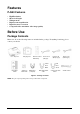
Features PJ550 Features • • • • • • High Resolution Short focal length Whisper-mode Digital zoom magnification Digital keystone correction Component video maximizes video image quality Before Use Package Contents Make sure all of the following items are included in the package. If anything is missing, please contact your dealer.
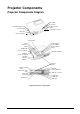
Projector Components Projector Components Diagram Zoom knob Focus ring Remote control sensor Slot for Kensington Lock Power switch Lens (with lens cap) AC power Intake ventilation Control panel Lamp indicator Temp indicator Power indicator Menu Reset Keystone Input Standby/ON Front foot adjuster Exhaust ventilation Air intake (for the cooling fan) Speaker Rear foot adjuster Interface panel Remote control sensor Component Video Y (In) CB/PB (In) CR/PR (In) RGB (In) Control (RS232) Audio (In, 3.
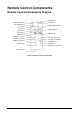
Remote Control Components Remote Control Components Diagram STANDBY/ON Button KEYSTONE Button VIDEO Button RGB Button MENU SELECT Button [Up] Button [Left] Button POSITION Button [Right] Button [Down] Button RESET Button MENU Button MAGNIFY [+] Button VOLUME [Up] Button MAGNIFY [-] Button VOLUME [Down] Button MAGNIFY [Off] Button AUTO Button FREEZE Button MUTE Button BLANK (Screen) Button Battery Holder Figure 3: Remote Control Components ViewSonic PJ550 4
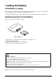
Loading the Battery Initial Battery Loading In the original packing, the battery is installed in the battery holder of the remote control with protective film (to preserve battery life while unit is not is use). Carefully pull out the protective film, then load the battery following to the procedure below. Replacing Remote Control Battery See the reverse side of the remote control. Figure 4: Battery 1 2 3 4 Pinch the groove and pull out battery holder. See graphic above. Remove the used battery.
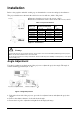
Installation Refer to the graphics and table on this page to determine the screen size and projection distance. The projection distances shown in the table below are for full size (1024 x 768 pixels). a Distance from the projector to the screen (+10%). b Distance from the lens center to the bottom of the screen (+10%). Screen Table 1: Projection Distance Screen Size Inches (m) Top View 40 (1.0) 60 (1.5) 80 (2.0) 100 (2.5) 120 (3.0) 150 (3.8) 200 (5.
Cabling Refer to the table below for connecting each terminal of the projector to a device. Table 2: Cabling Function Analog RGB input RS-232C communication Component video input S-video input Video input/ Audio input Terminal RGB CONTROL VIDEO Y VIDEO CB/PB VIDEO CR/PR S-VIDEO VIDEO AUDIO (L) AUDIO (R) 3.
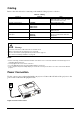
Example of System Setup Computer RGB (computer) RS232 Video/Audio cable DVD Player Component Video cable S-Video cable stereo-mini audio cable audio (L/R) portion of Video/Audio cable S-Video Player Notebook Computer Figure 8: System Setup Plug & Play This projector is VESA DDC 1/2B compatible. Plug& Play is possible by connecting to a computer that is VESA DDC (Display Data Channel) compatible.
Operations Power ON NOTE: Refer to “Example of System Setup” on page 8. 1 Make sure the power cord is connected correctly and lens cap has been removed. Set the Power 2 3 4 5 Switch to [I] ON. The unit is now in Standby mode and the POWER indicator LED turns a steady orange. Press the STANDBY/ON button on the control panel or the remote control. Warm-up begins and the power indicator blinks in green.
Basic Operation Table 3 below refers to buttons on the projector control panel and on the remote control. Items marked with (*) may be accessed from the projector control panel. Table 3: Basic Operation Item Description INPUT SELECT Select Input Signal (*) : press the INPUT Button. RGB > VIDEO > S-VIDEO > COMPONENT (>RGB) Select RGB Input: Press the RGB button. VIDEO/S-VIDEO/COMPONENT > RGB Select Video Input: Press the VIDEO button.
Table 3: Basic Operation (Continued) Item Description AUTO Automatic Adjustment (for RGB input): Press the AUTO button. Horizontal Position (H. POSIT), Vertical Position, (V. POSIT), Clock Phase (H. PHASE), and Horizontal Size (H. SIZE), are automatically adjusted. • Before using the AUTO feature, be sure to maximize the window of the application displayed on-screen. Automatic Adjustment (for Video Input): Press the AUTO button. A signal type appropriate for the input signal is selected automatically.
Table 4: Setup Menu (Continued) Item Actions/Description RGB Video/ S-Video V POSIT Down (Vertical Position) H POSIT (Horizontal Position) H PHASE (Horizontal Phase) H SIZE (Horizontal Size) SHARPNESS COLOR TINT COLOR BAL R (Color Balance Red) COLOR BAL B (Color Balance Blue) ASPECT (Aspect Ratio) X Left Right • Adjust to eliminate flicker. Small Large • If the Horizontal Size adjustment is excessive, the image many not be displayed correctly.
Input Menu SETUP INPUT AUTO RGB VIDEO HDTV IMAGE OPT. EXECUTE CANCEL The following functions are available when INPUT is selected on the menu. Select an item with the and buttons, and start operation. Table 5: Input Menu Item AUTO Description Operation Start/Stop: Press the button. Automatic Adjustment at RGB Input: Select the EXECUTE with the button. Horizontal position (H.POSIT), vertical position (V.POSIT), clock phase (H.PHASE), and horizontal size (H.SIZE) are automatically adjusted.
Image Menu The following adjustments and settings are available when IMAGE is selected on the menu. Select an item with the and buttons and start operation. Table 6: Image Menu Item Description BLANK Select Blank Screen Color: Select color with the buttons. The image is cleared when the BLANK mode is set with BLANK ON, or when there is no signal. In BLANK mode the entire screen is displayed in the selected color. MIRROR Operation Start/Stop: Press the buttons.
Options Menu The following adjustments and settings are available when OPT. is selected on the menu. Select an item with the and buttons and start operation. Table 7: Options Menu Item Description VOLUME Volume Adjustment: Use the MENU COLOR Select Menu Background Color: Select with the LANGUAGE Operation Start/Stop: Press the buttons. buttons. Select Menu Display Language: Select with the AUTO OFF Operation Start/Stop: Press the buttons. and buttons. buttons.
No Signal Menu The same adjustments and settings are available with the Image and Options menus when the MENU button is pressed during display of the “No INPUT IS DETECTED ON ***” or “SYNC IS OUT OF RANGE ON ***” message while no signal is received. VOLUME BLANK MIRROR START UP MENU COLOR LANGUAGE AUTO OFF SYNC ON G WHISPER Table 8: No Signal Menu Item VOLUME Description Volume Adjustment: Use the buttons. When this function is used, audio input is automatically switched to video.
Maintenance Lamp To order a new lamp unit (part number RLC-150-003) contact ViewSonic Customer Support. The estimated lamp life is 2000 hours. Before replacing the lamp, turn the Power Switch OFF, remove the power cord from the power outlet, and wait approximately 45 minutes until the lamp has cooled. CAUTION: The lamp may explode if handled at high temperatures. HIGH VOLTAGE HIGH TEMPERATURE HIGH PRESSURE Lamp WARNINGS • Dispose of the used lamp according to local regulations.
Replacing the Lamp When the indicator shows that there is zero (0) hours of lamp life remaining, the unit will automatically shut off within 10 minutes. If you see this message you should replace the lamp. However, you may replace the lamp anytime after the first warning message appears at 300 hours of remaining lamp life. 1 Switch the projector OFF, remove the power cord from the 2 3 4 5 6 7 8 power outlet, and wait at least 45 minutes for the unit to cool. Prepare a new lamp.
Air-Filter The air filter should be cleaned as described below at intervals of approximately 100 hours. 1 Switch the projector power supply OFF, and remove the power cord from the power outlet. 2 Clean the air filter with a vacuum cleaner. CAUTION • • • • Switch POWER OFF and remove the power cord from the power outlet before beginning maintenance work. Replace the air filter if contamination cannot be removed, or if it is damaged. Do not use the projector with the air filter removed.
Troubleshooting OSD Messages The messages as described below may appear on the screen at POWER ON. Take the appropriate measures when such messages appear. Table 9: OSD Messages Screen Message Meaning or Action Required CHANGE THE LAMP. AFTER REPLACING LAMP, RESET THE LAMP TIME. 1 The lamp will reach the end of its life in 300 hours. POWER is switched off automatically when the lamp reaches the end of its life. prepare a new lamp for installation. Always reset the lamp timer after replacing the lamp.
Table 10: Indicator Messages (Continued) POWER LAMP TEMP Meaning or Action Required indicator indicator indicator Blinks/ Lights red Lights red Turns off Lamp is not lit. The interior of the equipment may be too hot. Switch POWER OFF, wait 20 minutes until the equipment cools, and check whether the ventilation openings are blocked, whether the air filter is dirty, or whether the ambient temperature exceeds 95°F (35°C). And switch POWER ON again. Replace the lamp if the same problem occurs again.
Table 11: Symptom (Continued) Symptom Possible cause Remedy Page Audio is present but no video The projector is not correctly connected. Connect correctly. page 7 page 8 The brightness is set to minimum. Select BRIGHT and CONTRAST with the MENU button and page 11 Colors are pale and color matching is poor Color density and color matching are not correctly adjusted. Go to Setup and adjust color parameters. page 11 Images are dark Brightness and contrast are not correctly adjusted.
Specifications Technical Specifications Table 12: Specifications Item Specification PJ550 Liquid crystal projector Liquid crystal panel Panel Size Drive system Pixels 1.8 cm (0.7 inch) TFT active matrix 1024 horizontal x 768 vertical Lens Zoom lens F=2.0 - 2.3 f=17.7 -21.2 mm Lamp 150 W UHB (normal mode); 130 W UHB (whisper mode) Speaker 1.0 W Power Supply AC 100 ~ 120V, 2.7A I AC220 - 240V,1.
Customer Support Contact ViewSonic For technical support or product service, see the table below or contact your reseller. NOTE: You will need the product serial number. Country/Region Web site T = Telephone F = FAX Email United States viewsonic.com/ support T: (800) 688-6688 F: (909) 468-1202 service.us@ viewsonic.com Canada viewsonic.com/ support T: (800) 688-6688 F: (909) 468-1202 United Kingdom viewsoniceurope.com T: 0800 833 648 F: (01293) 643910 service.eu@ viewsoniceurope.
LIMITED WARRANTY VIEWSONIC Projector What the warranty covers: ViewSonic® warrants its products to be free from defects in material and workmanship during the warranty period. If a product proves to be defective in material or workmanship during the warranty period, ViewSonic will at its sole option repair or replace the product with a like product. Replacement product or parts may include remanufactured or refurbished parts or components.
Appendix Power Cord Safety Guidelines Caution: Use a power cable that is properly grounded. Always use an AC power cord that meets your country’s safety standard. USA .............................. UL Canada......................... CSA Germany ...................... VDE Switzerland ...................SEV Britain............................BASE/BS Japan ............................
Compliance Information for U.S.A. This equipment has been tested and found to comply with the limits for a Class B digital device, pursuant to part 15 of the FCC Rules. These limits are designed to provide reasonable protection against harmful interference in a residential installation. This equipment generates, uses, and can radiate radio frequency energy, and if not installed and used in accordance with the instructions, may cause harmful interference to radio communications.
Figures Figures Figure: 1 Package Contents ........................................................................................2 Figure: 2 Projector Components .................................................................................3 Figure: 3 Remote Control Components .......................................................................4 Figure: 4 Battery ..........................................................................................................5 Figure: 5 Screen Views ......