
Service manual

90
ViewSonic Corporation Confidential - Do Not Copy PJ513D-1
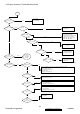
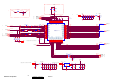
7. Block Diagram
Hardware Architecture
The Projector consists of the Source board, Main board, Keypad board, Fan board, EMI board,
PFC board, Ballast board, Door interlock switch, Color wheel index sensor board, and the
Thermal break sensor board. Please see Figure 1.
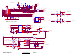
Source Board consists of audio phone jack, video RCA jack, S-video mini-DIN head, and USB
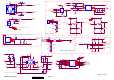
head. Main Board consists of RGB A/D conversion, Video decoder, DLP ASIC, Flash and RAM,
Motor driver, DMD Reset driver DAD2000, and IR receiver. Keypad Board consists of 8 keypads
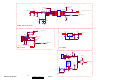
and 3 twice-color LEDs. Fan Board consists of DC/DC converter, Thermal Break circuit, Blower
Fan driver circuit, Rear Fan driver circuit, and the temperature sensing circuit. Power supply
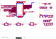
circuit consists of AC line EMI filter, Power Factor Correction circuit. Ballast Board consists of
Lamp synchronization circuit, Lamp lit feedback circuit, and Lamp power control circuit.
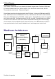
Hardware Architecture
Keypad Circuit
Input Source
Circuit
EMI
Filter
Main Operation Circuit
(DLP Image Processor
DDP2230)
(Video decoder TVP5147)
(DMD Reset driver DAD2000)
(A/D 9883)
(RAMBUS XDRAM)
Ballast
Module
Fan Driver
Circuit
PFC Circuit
Door
interlock
switch
From AC
socket
To Lamp
Thermal break
sensor Circuit
CW
Index
sensor
Lamp
Door
switch