
Service manual

45
ViewSonic Corporation Confidential - Do Not Copy PJ513D-1
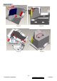
Fig. 5-10
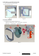
6. Assembly HSG ILL Module
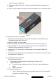
6.1 FM1 Assembly
I. FM1 must be placed on datum surfaces well and breach of FM1 must be face to inside
(Fig. 6-1)
II. Insert the” CLIP of FM1” into the hole on the HSG ILL and make sure ” CLIP of FM”
hook on the HSG ILL well (Fig. 6-2)
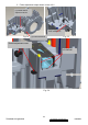
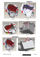
6.2 CM Assembly
III. Insert Clip CM Side and Clip CM Bottom first (Fig. 6-3,6-5)
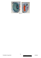
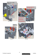
IV. Assemble CM to HSG ILL and to make CM contact three datum on the HSG ILL
Well (Fig. 6-8)
V. Assemble “CLIP of TOP” to the HSG ILL (Fig. 6-9)
VI. To check and make sure “ CLIP of CM” hooks the HSG ILL very Well (Fig.
6-4, 6-6,6-10)
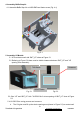
VII. Assemble Baffle Stop to HSG ILL and fasten screw (Fig. 6-10)
VIII. Paste Sponge tube AL on cannelure of HSG ILL(Fig. 6-11)
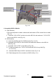
Pre-assy this screw not over
the bottom surface.
Pre-assy this screw not over
the side surface.
(1) Overfill Horizontal
Adjustment Screw
(2) Overfill Vertical
Adjustment Screw