&' /&' 0RQLWRU 8VHU *XLGH *XLGH GH O¶XWLOLVDWHXU *XtD GHO XVXDULR 0RGHO 1R 96
Content Safety Precautions ...................................................................................................5 Package Contents ....................................................................................................6 Optional accessories ................................................................................................................ 6 Parts Name and Functions ......................................................................................7 Front View ....
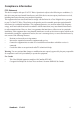
&RPSOLDQFH ,QIRUPDWLRQ )&& 6WDWHPHQW 7KLV GHYLFH FRPSOLHV ZLWK SDUW RI )&& 5XOHV 2SHUDWLRQ LV VXEMHFW WR WKH IROORZLQJ WZR FRQGLWLRQV WKLV GHYLFH PD\ QRW FDXVH KDUPIXO LQWHUIHUHQFH DQG WKLV GHYLFH PXVW DFFHSW DQ\ LQWHUIHUHQFH UHFHLYHG LQFOXGLQJ LQWHUIHUHQFH WKDW PD\ FDXVH XQGHVLUHG RSHUDWLRQ 7KLV HTXLSPHQW KDV EHHQ WHVWHG DQG IRXQG WR FRPSO\ ZLWK WKH OLPLWV IRU D &ODVV % GLJLWDO GHYLFH SXUVXDQW WR SDUW RI WKH )&& 5XOHV 7KHVH OLPLWV DUH GHVLJQHG WR SURYLGH UHDVRQDEOH SURWHFWLRQ DJDLQV
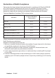
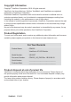
'HFODUDWLRQ RI 5R+6 &RPSOLDQFH 7KLV SURGXFW KDV EHHQ GHVLJQHG DQG PDQXIDFWXUHG LQ FRPSOLDQFH ZLWK 'LUHFWLYH (& RI WKH (XURSHDQ 3DUOLDPHQW DQG WKH &RXQFLO RQ UHVWULFWLRQ RI WKH XVH RI FHUWDLQ KD]DUGRXV VXEVWDQFHV LQ HOHFWULFDO DQG HOHFWURQLF HTXLSPHQW 5R+6 'LUHFWLYH DQG LV GHHPHG WR FRPSO\ ZLWK WKH PD[LPXP FRQFHQWUDWLRQ YDOXHV LVVXHG E\ WKH (XURSHDQ 7HFKQLFDO $GDSWDWLRQ &RPPLWWHH 7$& DV VKRZQ EHORZ 3URSRVHG 0D[LPXP &RQFHQWUDWLRQ $FWXDO &RQFHQWUDWLRQ /HDG 3E 0HUFXU\ +J
,PSRUWDQW 6DIHW\ ,QVWUXFWLRQV 5HDG WKHVH LQVWUXFWLRQV FRPSOHWHO\ EHIRUH XVLQJ WKH HTXLSPHQW .
&RS\ULJKW ,QIRUPDWLRQ &RS\ULJKW 9LHZ6RQLF &RUSRUDWLRQ $OO ULJKWV UHVHUYHG 9LHZ6RQLF WKH WKUHH ELUGV ORJR 2Q9LHZ 9LHZ0DWFK DQG 9LHZ0HWHU DUH UHJLVWHUHG WUDGHPDUNV RI 9LHZ6RQLF &RUSRUDWLRQ 'LVFODLPHU 9LHZ6RQLF &RUSRUDWLRQ VKDOO QRW EH OLDEOH IRU WHFKQLFDO RU HGLWRULDO HUURUV RU RPLVVLRQV FRQWDLQHG KHUHLQ QRU IRU LQFLGHQWDO RU FRQVHTXHQWLDO GDPDJHV UHVXOWLQJ IURP IXUQLVKLQJ WKLV PDWHULDO RU WKH SHUIRUPDQFH RU XVH RI WKLV SURGXFW ,Q WKH LQWHUHVW RI FRQWLQXLQJ SURGXFW LPSURYHPHQW 9LHZ6RQL
Safety Precautions FOR OPTIMUM PERFORMANCE, PLEASE NOTE THE FOLLOWING WHEN SETTING UP AND USING THE LCD COLOR MONITOR: • DO NOT REMOVE MONITOR BACK COVER. There are no user serviceable parts inside and opening or removing covers may expose you to dangerous shock hazards or other risks. Refer all servicing to qualified service personnel. • Do not spill any liquids into the cabinet or use your monitor near water.
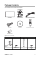
Package Contents Your new CD4225 monitor box should contain the following: LCD monitor Quick Start Guide Power cord for North America VGA cable CD Wizard Wireless Remote Control AAA battery (x 2) Optional accessories Stand (STND-013) Monitor stand (x 2) ViewSonic CD4225 M4 screw for stand installation (x 8) Speaker External speaker (x 2) M3 screw for speaker installation (x 6) 6
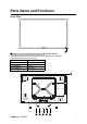
Parts Name and Functions Front View 1 1 Remote control sensor/Ambient light sensor/Power LED indicator • Receives the signal from the wireless remote control. • Automatically detects ambient lighting condition and adjusts screen brightness. • Indicates the power status of the monitor.
1 Carrying handles - Use these handles to move the LCD monitor while installing. 2 Power button ( 3 4 5 6 ) - Turns the LCD monitor’s power on or put it to standby. This button does not isolate the LCD monitor from AC power input. To completely cut off the AC power supply, use the main power switch on the terminal panel. Exit button - Acts as the EXIT button to move to previous menu with OSD menu. PLUS (+) button - Acts as the (+) button to increase the adjustment with OSD menu.
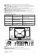
3 AUDIO-IN R/L To input audio signals from external equipment such as a VCR or DVD player. 4 HDMI To input digital RGB signals from a computer. * This connector does not support analog input. Audio is supported via HDMI. 5 DVI-IN To input digital RGB signals from a computer. *This connector does not support audio input. The audio signal should be connected to the LINE-IN jack. 6 DVI-OUT To output digital RGB signals from DVI-IN to another monitor.
Remote Control 2 1 3 1 MUTE button To switch the mute function on/off. 2 Power button Switches the power on/off. *If the Power indicator on the monitor is not glowing, then no controls will work. 3 Number buttons These buttons are not used and do not work. 5 4 6 4 UP button Acts as button to move the highlighted area up to select the adjustment with OSD menu. 7 8 5 INPUT button Selects from input signal: [VGA], [DVI], [HDMI] and [YPbPr].
Installing the Remote Control Batteries The remote control is powered by 1.5V AAA batteries. To install or replace batteries: 1. Press and slide to open the cover. 2. Align the batteries according to the (+) and (-) indications inside the case. 3. Replace the cover. CAUTION: Incorrect use of batteries can result in leaks or bursting. Be careful especially about the following points. • Place “AAA” batteries matching the + and - signs on each battery to the + and - signs of the battery compartment.
Setup Procedure 1. Determine the installation location CAUTION: DO NOT ATTEMPT TO INSTALL THE LCD MONITOR BY YOURSELF. Installation of your LCD monitor must be done by a qualified technician. Contact your dealer for more information. CAUTION: MOVING OR INSTALLING THE LCD MONITOR MUST BE DONE BY TWO OR MORE PEOPLE. Failure to follow this caution may result in injury if the LCD monitor falls. CAUTION: Do not mount or operate the monitor upside down, face up, or face down.
• Placing the monitor in portrait position will shorten the average life of the LCD backlight. • Operational Environment (Temperature) shall be limited, as shown below: Operational Environment Temperature 5 - 35 C / 41 - 95 F Humidity 20 - 80% (without condensation) Please orientate the monitor in the direction shown below: Do not place monitor in landscape in any other manner. How to set-up 1. Remove the stands (legs) if attached. 2. The ViewSonic logo should be on the LEFT side when facing the monitor.
How to Mount and Attach Options to the LCD Monitor Lay the protective sheet on a table, which was wrapped around the monitor when it was packaged, beneath the screen surface so as not to scratch the screen face. 400mm 200mm 200mm This device cannot be used or installed without the Tabletop Stand or other mounting accessory. Failure to follow correct mounting procedures could result in damage to the equipment or injury to the user or installer.
Ventilation Requirements for enclosure mounting To allow heat to disperse, leave space between surrounding objects as shown in the diagram below. 100mm 100mm 100mm 100mm To avoid monitor from falling Take measures to prevent the monitor from falling over in case of an earthquake or other disaster to lessen the probability of injury and damage resulting from fall.
Connections Before making connections: • First turn off the power of all the attached equipment and make connections. • Refer to the user manual included with each separate piece of equipment.
Connecting a Personal Computer Connecting your computer to your LCD monitor will enable you to display your computer's screen image. Some video cards may not display an image correctly. Connect the LCD Monitor to a Personal Computer • To connect the VGA IN connector (mini D-sub 15 pin) on the LCD monitor, use a PC - Video RGB signal cable (mini D-sub 15 pin to mini D-sub 15 pin). • When connecting one or more LCD monitors, use the VGA OUT connector (mini D-sub 15 pin).
Connecting with Digital Interface Equipment Connections can be made with equipment that is equipped with a digital interface compliant with the DVI (Digital Visual Interface) standard. Connect the LCD Monitor to a Computer with a Digital Output • The HDMI connector accepts a HDMI cable or a DVI-D to HDMI cable. • The HDMI connector can connect to HDMI output or DVI-D output of PC. • To maintain display quality, use a cable with a quality prescribed by HDMI and DVI standards.
Connecting a DVD Player with component out Connecting your DVD player to your LCD monitor will enable you to display DVD video. Refer to your DVD player owner’s manual for more information. Connect the LCD Monitor to a DVD Player • Connect the Y Pb Pr IN jacks of the LCD monitor to the Y Pb Pr output of the DVD player. Alternatively, you can also use a HDMI cable to connect the HDMI jack of the LCD monitor to the HDMI output of the DVD player. • The AUDIO-IN jacks can be used for audio input.
Connecting to External Speakers This LCD monitor has a built-in 6W+6W amplifier, so you can connect the optional external speakers to the LCD monitor directly. Refer to your external speakers’ owner's manual for more information. Connect the LCD Monitor to External Speakers • Connect the lead wires of the external speakers to the SPEAKER OUT jacks of the LCD monitor. Do not reverse the audio left and right jacks.
Basic Operation Power ON and OFF Modes The main power of the LCD monitor can be turned on or off using the main power switch on the terminal panel. With the main power of the LCD monitor turned on, you can toggle between the on and standby modes using the following two options: 1. Pressing the Power button. NOTE: Before pressing the power button, be sure to connect the supplied power cord to the LCD monitor. 2. Using the remote control.
Selecting a video source Normally the CD4225 LCD monitor automatically searches for available video sources after it is turned on. You can also manually select one if multiple video sources are connected to the LCD monitor. To select a video source using the control panel: 1. Press the Menu/Enter button on the control panel to display the OSD menu. 2. Press the PLUS (+) or MINUS (-)/Auto button to select Input, and then press the Menu/Enter button. 3.
OSD (On-Screen-Display) Controls 1. Press the MENU button to open Main menu. 2. Press the or button to select sub-menu. 3. Press the ENTER button to decide. Remote Control 4. Press the or button to select function, or control which you like. 5. Press the EXIT button to exit. 1. Press the Menu/Enter button to open the Main menu. 2. Press the PLUS (+) or MINUS (-)/Auto button to select sub-menu. 3. Press the Menu/Enter button to decide. Control Panel 4.
OSD Screen Picture VGA Setting Option Input Audio Special Diagnostic 1360 x 768 Picture Mode 60Hz Auto Adjustment Language VGA Contrast Clock OSD H. Pos. DVI Brightness Phase OSD V. Pos. HDMI YPbPr Color Temp H. Position OSD Timer Temp Adjust V.
Picture Picture Mode Contrast Brightness Color Temp Temp Adjust Sharpness Standard 1360 x 768 60Hz Picture Mode • Allows you to choose from the following preset picture modes: Standard, Vivid, Cinema and User. • Press the ENTER button on the remote control, or the Menu/Enter button on the control panel to change selection. Contrast • Adjusts the image brightness in relation to the input signal. • Press the or PLUS (+) button to increase contrast.
VGA Setting NOTE: For VGA input only. Auto Adjustment Clock Phase H. Position V. Position 1360 x 768 60Hz Auto Adjustment • Use this function to let the monitor automatically optimize the display of PC input image. • Press the ENTER button on the remote control, or the Menu/Enter button on the control panel to execute this function. Clock • Press the or PLUS (+) button to expand the width of the image on the screen the right.
Option Language OSD H. Pos. OSD V. Pos. OSD Timer Ambient Light LED Indicator Auto Detection 1360 x 768 60Hz Language • Allows you to select a preferred language for the OSD menu. • Press the / or PLUS (+)/MINUS (-)/Auto button to select a language. OSD H. Pos. • Adjusts the horizontal position of the OSD menu. • Press the or PLUS (+) button to move the OSD menu right. • Press the or MINUS (-)/Auto button to move the OSD menu left. OSD V. Pos. • Adjusts the vertical position of the OSD menu.
Input VGA DVI HDMI YPbPr 1360 x 768 60Hz VGA • Selects the signal connected to the VGA IN input terminal as the input source. DVI • Selects the signal connected to the DVI-IN input terminal as the input source. HDMI • Selects the signal connected to the HDMI input terminal as the input source. YPbPr • Selects the signal connected to the Y Pb Pr IN input terminal as the input source.
Audio Volume Mute 1360 x 768 60Hz Volume • Adjusts the audio volume. • Press the or PLUS (+) button to increase volume. • Press the or MINUS (-)/Auto button to decrease volume. Mute • Turns audio off temporarily. • Press the ENTER button on the remote control, or the Menu/Enter button on the control panel to turn this function on or off.
Special Aspect Ratio Overscan Power Save Image Retention Auto Adjustment Monitor ID Reset Original 1360 x 768 60Hz Aspect Ratio • With this function, you can choose to let the LCD monitor display the input image in its original aspect ratio (when Original is selected), or force the LCD monitor to fill the input image on the entire display area (when Full is selected). • Press the ENTER button on the remote control, or the Menu/Enter button on the control panel to change selection.
monitors using this function. ID numbers 1 to 26 are selectable. It is recommended to assign sequential ID numbers from 1 and up. • Press the ENTER button on the remote control, or the Menu/Enter button on the control panel, and then press the / (or PLUS (+)/MINUS (-)/Auto) button to change the ID number. Reset • If activated, all OSD settings (except the Language setting) will be restored to the factory settings.
Diagnostic Thermal Operating Ambient 5V Detect 12V Detect xx C xxhr xxLux x.xx V x.xx V Thermal • Displays current temperature inside the LCD monitor. Operating • Displays the operating hours of the LCD monitor since it was first turned on. Ambient • Displays current ambient brightness around the LCD monitor. 5V Detect • Displays current 5V voltage detection result. 12V Detect • Displays current 12V voltage detection result.
For Long Life Use of Public Display < Image Sticking of LCD Panel > When LCD panel is operated continuously for long hours, a trace of electric charge remains near the electrode inside LCD, and residual or “ghost” image of previous image may be observed. (Image Persistence) Image Persistence is not permanent, but when fixed image is displayed for long period, ionic impurities inside LCD are accumulated along the displayed image, and it is observed permanently.
Controlling the LCD monitor via RS232C Remote Control This LCD monitor can be controlled by connecting a personal computer with a RS-232C terminal. Functions that can be controlled by a personal computer are: Connection LCD Monitor + PC NOTE: Two kinds of RS-232 protocols are provided: serial connection and non-serial connection.
Appendix: Installing stands How to install stands 1. Spread the protective sheet on the flat surface, such as a desk. Place monitor on the protective sheet. 2. Place the stands on the monitor as shown. NOTE: Install the stands so that their longer portions come to the front. 3. Use the M4 screws and a suitable screwdriver to secure the stands on the LCD monitor.
Features Signage-friendly Design • All metal (aluminum) construction • Industrial-grade superior reliability • VESA mounting compliance with carrying handles • Various mounting schemes for player carriers PC-Based Multi-panel Management • Full-function display controls • Real-time diagnostics for detecting voltage and temperature ViewSonic CD4225 36
Troubleshooting No picture • The signal cable should be completely connected to the display card/computer. • The display card should be completely seated in its slot. • Monitor and computer power should be switched ON. • Check to make sure that a supported mode has been selected on the display card or system being used. (Please consult display card or system manual to change graphics mode.) • Check the monitor and your display card with respect to compatibility and recommended settings.
Specifications Product Specifications Product specifications LCD Module Frequency Pixel Clock Viewable Size Input Signal PC Input: Diagonal: Pixel Pitch: Resolution: Color: Brightness: Analog Input Digital Input 42.02" / 106.73 cm 0.4845 mm 1920 x 1080 dots Over 16 million colors (depending on video card used) 500 cd/m2 (typ.) Contrast Ratio: 1500:1 (typ.) Response time: 5 ms (typ. G to G) View Angle: Up and Down 178 , Left and Right 178 (typ.) @CR>10 Design View Distance: 1100 mm / 43.
Supported Input Signal Resolution Input source Resolution YPbPr VGA HDMI DVI 640 x 480 @ 60Hz 720 x 400 @ 70Hz 800 x 600 @ 60Hz 1024 x 768 @ 60Hz 1280 x 768 @ 60Hz 1280 x 960 @ 60Hz 1280 x 1024 @ 60Hz 1366 x 768 @ 60Hz 1600 x 1200 @ 60Hz 1920 x 1080 @ 60Hz 576i (50Hz) 480i (60Hz) 480p (60Hz) 576p (50Hz) 720p (50Hz) 720p (60Hz) 1080i (50Hz) 1080i (60Hz) 1080p (50Hz) 1080p (60Hz) Note: • : supported • Blank: not supported ViewSonic CD4225 39
1RWH IRU 'DLV\ &KDLQ &RQQHFWLRQ :KHQ FRQQHFWLQJ PXOWLSOH PRQLWRUV LQ D GDLV\ FKDLQ FRQ¿JXUDWLRQ SOHDVH UHIHU WR WKH WDEOH EHORZ IRU WKH PD[LPXP QXPEHU RI PRQLWRUV WKDW FDQ EH GHSOR\HG GHSHQGLQJ RQ WKH VLJQDO W\SH DQG UHVROXWLRQ XVHG )RU H[DPSOH LI \RX XVH 9*$ DV WKH VLJQDO W\SH DQG VLJQDO UHVROXWLRQ LV [ # +] WKHQ \RX FDQ FRQQHFW XS WR PRQLWRUV LQ D GDLV\ FKDLQ FRQ¿JXUDWLRQ ,W LV UHFRPPHQGHG WKDW \RX XVH 9*$ DV WKH VLJQDO W\SH IRU LQSXW RXWSXW FRQQHFWLRQ LQ D GDLV\ FKDLQ FRQ¿JXUDWLRQ
&XVWRPHU 6XSSRUW )RU WHFKQLFDO VXSSRUW RU SURGXFW VHUYLFH VHH WKH WDEOH EHORZ RU FRQWDFW \RXU UHVHOOHU 1RWH
/LPLWHG :DUUDQW\ 9,(:621,& /&' 0RQLWRU :KDW WKH ZDUUDQW\ FRYHUV 9LHZ6RQLF ZDUUDQWV LWV SURGXFWV WR EH IUHH IURP GHIHFWV LQ PDWHULDO DQG ZRUNPDQVKLS XQGHU QRUPDO XVH GXULQJ WKH ZDUUDQW\ SHULRG ,I D SURGXFW SURYHV WR EH GHIHFWLYH LQ PDWHULDO RU ZRUNPDQVKLS GXULQJ WKH ZDUUDQW\ SHULRG 9LHZ6RQLF ZLOO DW LWV VROH RSWLRQ UHSDLU RU UHSODFH WKH SURGXFW ZLWK D OLNH SURGXFW 5HSODFHPHQW SURGXFW RU SDUWV PD\ LQFOXGH UHPDQXIDFWXUHG RU UHIXUELVKHG SDUWV RU FRPSRQHQWV +RZ O
0H[LFR /LPLWHG :DUUDQW\ 9LHZ6RQLF /&' &RPPHUFLDO 0RQLWRU :KDW WKH ZDUUDQW\ FRYHUV 9LHZ6RQLF ZDUUDQWV LWV SURGXFWV WR EH IUHH IURP GHIHFWV LQ PDWHULDO DQG ZRUNPDQVKLS XQGHU QRUPDO XVH GXULQJ WKH ZDUUDQW\ SHULRG ,I D SURGXFW SURYHV WR EH GHIHFWLYH LQ PDWHULDO RU ZRUNPDQVKLS GXULQJ WKH ZDUUDQW\ SHULRG 9LHZ6RQLF ZLOO DW LWV VROH RSWLRQ UHSDLU RU UHSODFH WKH SURGXFW ZLWK D OLNH SURGXFW 5HSODFHPHQW SURGXFW RU SDUWV PD\ LQFOXGH UHPDQXIDFWXUHG RU UHIXUELVKHG SDUWV RU FRPSRQHQWV DFFHVVRULHV +RZ ORQJ WK
&RQWDFW ,QIRUPDWLRQ IRU 6DOHV $XWKRUL]HG 6HUYLFH &HQWUR $XWRUL]DGR GH 6HUYLFLR ZLWKLQ 0H[LFR 1DPH DGGUHVV RI PDQXIDFWXUHU DQG LPSRUWHUV 0p[LFR $Y GH OD 3DOPD 3LVR 'HVSDFKR &RUSRUDWLYR ,QWHUSDOPDV &RO 6DQ )HUQDQGR +XL[TXLOXFDQ (VWDGR GH 0p[LFR 7HO KWWS ZZZ YLHZVRQLF FRP OD VRSRUWH LQGH[ KWP 1Ò0(52 *5$7,6 '( $6,67(1&,$ 7e&1,&$ 3$5$ 72'2 0e;,&2 +HUPRVLOOR 'LVWULEXFLRQHV \ 6HUYLFLRV &RPSXWDFLRQDOHV 6$ GH &9 &DOOH -XDUH] ORFDO &RO %XJDPELOLDV &