INTERAaM View-Master® Interactive Vision™ Television System (VMIV) Installing and Operating Instructions Note to Parents/Guardians Setting Up Operating the System Trou ble·Shooting Care and Maintenance 2 6 20 22 24
CAUTION-ELECTRICALLY OPERATED PRODUCT: Not recommended for children under 3 years of age. As with all electrical products, precautions should be observed dUring handling and use to prevent electric shock. AC Adapter: Input: 120 VAC, 60 Hz. Output: 16 VAC, C.T., 800 rnA. System Requirements: 1. The VCR must be VHS format. 2. The VCR must have AUDIO OUT and VIDEO OUT jacks. Almost all VCRs are equipped with these, but you should check the back of your VCR to be sure.
I I I I I I CONTENTS Note to Parents/Guardians 2 Important Safety Tips 5 Setting up 6 What We Provide 6 What You Provide 7 Step- By-Step Installation 8 Abbreviated Instructions (for the technically inclined) 9 18 A Note on Stereo Operating the System 20 Starting Up Starting and Stopping Replaying an Interaction Pausing Rewinding and Fast Forwarding Adjusting Sound Levels Quitting Trouble-Shooting I 20 20 20 21 21 21 21 ~ 22 Care and Maintenance 24 FCC Regulations 25
NOTE TO PARENTS/GUARDIANS Dear Parents/Guardians: View-Master® Interactive Vision™ Television System (VMIV) offers a two-way television viewing experience that's both entertaining and educational. Your child will play games, constnlct songs and stories, and respond to questions asked by his or her favorite TV and movie characters, who will react differently according to the answers. To help your child get the most out of VMIV, please read this booklet completely before you operate the system.
I I I I I' I I I NOTE TO PARENTS/GUARDIANS • TROUBLE-SHOOTING. In the unlikely event you have a problem in operating the View- Master® Interactive Vision™ Television System, this section provides suggestions for remedying the problem. We also recommend that you remain with your child the first time he or she operates the system. That way, you will be able to share in the child's enjoyment as well as ensure that everything is working smoothly.
4
IMPORTANT SAFETY TIPS Important Safety Tips • Observe Warnings. Read all safety and operating instructions before operating the system, and all warnings on system components should be observed. • Power Sources. The system should be connected only to the AC Adapter supplied with this product (see SETTING UP). • Object and Liquid Entry. Care should be taken so that small objects do not fall and liquids are not spilled into system components. • Temperature.
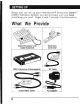
SETTING UP Before you can set up your View- Master® Interactive Vision ™ (VMN} Television System, you should make sure you have everything you need. Pages 6 and 7 provide this information.
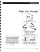
• • SETTING UP I I What You Provide TV with VHF IN (also called ANT in, RF in, or TV in) RF cable that is presently attached to the VHF OUT jack on your VCR. I Note: There are two types of RF connectors, screw-on and push-on. Either type will worK fine. Note: if your VCR does not have Audio Out and Video Out jacks, please call 1-800-292-9843, between the hours of 7:30 a.m. and 4:00 p.m.
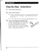
SETTING UP Step-By-Step Installation 1. Turn off your VCR and TV. 2. Adjust switch settings: 3. 8 • Channel switches on the back of VCR and the View-Master® Interactive Vision™ Television /stem (VMN) should both be set to 3 or 4. • The 1V should be tuned to the same channel (either 3 or 4). Connect the Electronic Controller Unit. Take the black cable attached to the front of the VMN Video Processor, and attach it to the Electronic Controller Unit with its joystick and buttons.
I I I SETTING UP 4. Find the cable attached to your VCR at the jack labelled VHF OUT. (Depending on the VCR, this jack may also be called RF OUT, OUT to IV, IV OUT, or something similar.) See what the other end of that cable is attached to. I I I If the cable connects... A. ... directly to your 1V (for stereo lV, see D. I below) See Page 10. I B. ... to a cable converter box See Page 12. 1 - C. ...
SETTING UP Configuration A: Your VCR connects directly to your TV. Your current configuration looks something like this: ~":,:,:,:,.,:":,:,:":,.., :,"""'S ~ ~ ~ TV " d)~.. VHF IN ~ @®~~ """"""""""""~ OR ...... --- ~~ Dis~onnect ~"""""""""""""""""~Antenna da01d}=~~VHFOUT VHFIN~~o~able this cable at VCR ~ eAUDIO OUT ~ ~ t:!fU ~VIDEO OUT VCR ~~ S ~""""""""""""""""""" Configuration A, Without VMIV • Disconnect the cable attached to the VHF OUT jack on the VCR.
I I I SETTING UP • Attach the other cables as illustrated below. ~",..\""",..\""""" ., ., ." """",.." "",.." ,..,~ ~ ~O VHF OUT ~~ ~~ ~ 4'\AUDIO OUT I I VHF INQJJ ~~ ~ ... ~W1 VCR~ ~
SETTING UP Configuration B: Your VCR connects to a cable converter box. If the cable attached to the VHF OUT jack on your VCR goes to a cable converter box instead of straight to the 1V. your current configuration looks something like this: """"""""""""""""",,~ ~~ ~ 0I VHF OUT ~~ ~ ..,AUDIO OUT ~ VHF IN ~ ~ ~~ Antenna or cable ... ~ ~~
SETTING UP • Attach the other cables as illustrated below. ~""""'. " """"""""" . " ,""""'" """"'~ Ant. 0 r ~""""""""~""""""""""~ ~ ~VHF OUT ~~ ~ ~ CABLE IN~~~ CON'VERTER ~~ s~ ~tQl0UT BOX ~ s ... To TV ~ _AUDIO OUT ~ ~ Cable VHFINtQI~"'" ~ ~~
SETTING UP Configuration C: Your VCR connects to a switch box. If the cable attached to the VHF OUT jack on your VCR goes to a switch box instead of straight to the 1V, your current configuration looks something like this: ~"""':,.,:,:,:,,",.., :,:,,""",..,:,,'.,. . ,:,:,,":,:,:,:,,~ ~ ~S ~ ~ ~ T.TV From cable converter box, electronic ~~ game, home computer, etc. IN ~~~ SWITCH BOX ~((JOUT S ~ ~ IN®l~ ~~"""""""""""""""""'~ ...
SETTING UP I • ~""" ., :,:,:,"'.., :,:,':,:,""'.., ., :,'..,:,:,.., .,:,.,:,..,:" From cable converter box, electronic ~ ~ ~ ~ ~ I I I I I I I I I Attach the other cables as illustrated below. To TV • ~ ~ ~ ~~ game, home computer, etc. IN IQJP~ ,. ~ ~ ~O VHF OUT SWITCH BOX ~ ~ ~d) OUT IN ~~ ~~""""""""""""""""""" (Must be switched to VMIV input) . ~ C!DVIDEO OUT ~ ~"""""""""""""""""~ CH.: DC) (Q) li:l AUD RFOUT ~ Cable ~~ VHFIN(Q)~~ ~ AS.
SETTI~JG UP Configuration 0: Your VCR connects to a stereo TV, with audio and video cables also attached. If the cable attached to the VHF OUT jack on your VCR goes to a stereo 1V, and you also have audio and video cables connecting the VCR to the 1V, your current configuration looks something like this: ~'''''''''''''''''''''''''''''':~ ~ ~s ~"""""""""""""'''''''''''~ Antenna ~~ ~ or cable ~ TV AUDIO 1 ~ t)AUDIO 1 OUT ~ AUDIO 2 IN..
I I SETTING UP • Attach cables as illustrated below. '(Note: To maintain stereo capability, please read "A Note on Stereo" on pages 18-19.) See "A Note on Stereo" on page 18.
SETTING UP A Note on Stereo No matter what type of stereo configuration you have, you will be able to use the View-Master® Interactive Vision™ Television System (VMIV) with no problem. • If your TV has MTS (multi-channel television sound) capability, broadcast stereo will be transmitted to the TV through the RF cable as normal.
I I SETTING UP A Note on Stereo (continued) ~"""""""""""""""""~ ~~ ~ 0J;;IVHF OUT ~ .4'\AUDIO 1 OUT ~~ s AS.\ ~VAUDIO 2 OUT Ant. or ~ Cab1le VHF INcQJ ~~ ~ ~ s ~ ~t5.\ VCR~~ ~ \!U VIDEO OUT s..""""""""""""""""",\ VMIV CH': 123 [L] AUD EJ 6) ~ ~ AF OUT RF IN AUDIO IN e VIDEO IN 1m AC • Configuration 0, With VMIV and Stereo I I I • When the Y-connectors have been installed, you will have two different sets of input to the 1V.
OPERATING THE SYSTEM Starting U'p 1. Slide the square switch to tum the View- Master® Interactive Vision™ Television System (VMIV) on. 2. Tum the TV and VCR on. Tune the TV to channel 3 or 4. to match the switch settings on your VCR and VMIV. 3. Insert the interactive videocassette into the VCR. 4. Press "Play" on the VCR. (Note: In these operating instructions. all videotape operations. such as playing. pausing. rewinding. and fast forwarding. apply to controls on your VCR.) 5.
- - - - - - - OPERATING THE SYSTEM Paus,ing • The best place to pause is when you can see the yellow stripes: the system will function normally when you resume play. If you pause at other places on the tape. some interactive features of the tape may be temporarily suspended. Remember. pausing should not be used frequently. because it will gradually degrade any videotape.
TROUBLE-SHOOTING Symptom Possible Remedy Make sure the TV and VCR are both turned on and the power cords are plugged in. I get no picture on my IV screen. Turn the VMIV on and off; see if this has any ,effect on the picture. If it has no effect, your cables are not connected properly. Return to the appropriate SEITING UP diagram to double-check your cable connections. I I I get a clear picture but no sound. I Check your TV volume. The audio cable may not be connected properly.
I I I I I I TROUBLE-SHOOTING Symptom Possible Remedy VMN is turned off. but my 1V only works on Channel 3. Turn off your VCR. Make sure the VMIV Video Processor is turned on. I The interactive tape plays, but I : can't get any interaction. II I With VM1V connected, I can't get stereo on the 1V. Refer to "A Note on Stereo." page 18. I I Interactive functions don't work. Start the interactive tape at the beginning or at the yellow stripes.
CARE AND MAINTENANCE Care and Maintenance • Do not use any Power Adapter other than the AC Adapter included with the View-Master® Interactive Vision TYI Television System (VMIV). • Always turn the Video Processor Power Switch OFF when not in use. • It is not recommended that you unplug the Remote Control Cable from the Electronic Controller Unit once it is connected. However, if your Electronic Controller Unit needs cleaning, turn off the Video Processor and unplug the Remote Control Cable.
I I I II II FCC REGULATIONS FCC Regulations This system generates and uses radio frequency energy, and if not installed and used properly, that is, in strict accordance with the manufacturer's instructions, may cause interference to radio and television reception.
View-Master® Interactive Vision™ Television System and Program Software ©1988 IDEAL. INC .. a subsidiary of View-Master Ideal Group. Inc .. Box 100. Portland. OR 97207 View-Master® Interactive Vision™ is based upon concepts developed by AC1V. Inc. U.S. and Foreign Patents Pending. View-Master® Interactive Vision™ Television System Installing and Operating Instructions ©1988 View-Master Ideal Group. Inc. Printed in U.S.A. Assembled in the U.S.A. from domestic and foreign components.