Installation and service instructions VIESMANN for contractors Vitotrol 100 Type UTDB-RF2 Room temperature controller with digital time switch and wireless receiver For applicability, see the last page VITOTROL 100 5457 286 GB 2/2010 Please keep safe.
Safety instructions Safety instructions Please follow these safety instructions closely to prevent accidents and material losses. Safety instructions explained Danger This symbol warns against the risk of injury. ! Please note This symbol warns against the risk of material losses and environmental pollution. Note Details identified by the word "Note" contain additional information.
Safety instructions Safety instructions (cont.) If you smell flue gas Danger Flue gas can lead to life-threatening poisoning. ■ Shut down the heating system. ■ Ventilate the boiler room. ■ Close all doors leading to the living space. Working on the system ■ When using gas as fuel, also close the main gas shut-off valve and safeguard against unauthorised reopening. ■ Isolate the system from the power supply and check that it is no longer 'live', e.g.
Index Index Installation instructions Preparing for installation Function................................................................................................................ Installation location............................................................................................... 5 5 Installation sequence Installing and connecting the wireless receiver.................................................... Installing the Vitotrol 100.....................................................
Preparing for installation Function Installation Through its integral room temperature sensor and in conjunction with the wireless receiver, the Vitotrol 100, type UTDB-RF2, achieves a constant room temperature. During the selected periods, there is a changeover between operation with standard room temperature "Comfort" and operation with reduced room temperature "Eco" or "Reduced". DHW is provided during the selected periods.
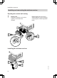
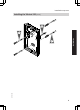
Installation sequence Installing and connecting the wireless receiver Opening the control unit casing ! Please note Electronic modules can be damaged by electrostatic discharges. Before beginning work, touch earthed objects, such as heating or water pipes, to discharge static loads. 2. 2x 3. 1. 4x Installing the wireless receiver 2. 1. 8 6 Q ë r w 5457 286 GB 3.
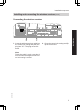
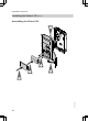
Installation sequence Installing and connecting the wireless receiver (cont.) Connecting the wireless receiver X7 GAS X20 1. Insert the wireless receiver cable into the control unit casing and push the plug into "X7". The plug must click home. PUMP FAN X9 ?LN 1 LN 2. Close the control unit casing and flip up the control unit. 5457 286 GB Note Route the cable in such a way that it does not become trapped as the control unit casing is closed.
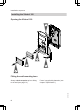
Installation sequence Installing the Vitotrol 100 Opening the Vitotrol 100 5. 4. 3. 1. 2. Fitting the wall mounting base Power is supplied by batteries (see chapter "Specification"). 5457 286 GB Always check reception prior to fitting to the wall (see page 12).
Installation sequence Installing the Vitotrol 100 (cont.) 2. Installation 3. 5457 286 GB 1.
Installation sequence Installing the Vitotrol 100 (cont.) Assembling the Vitotrol 100 1. 2. 3. 5. 5457 286 GB 4.
Commissioning Commissioning the Vitotrol 100 1. Open the hinged flap. 2. Use a pointed object to press "Reset". 3. Select language with / . 4. Confirm with OK. 5. Set current date and time with / . 6. Confirm with OK. Commissioning the wireless receiver 8 Q ë rw B Note If LED r flashes, the wireless receiver has not recognised the signal from the Vitotrol 100. If this is the case, change the address code (see page 13).
Commissioning Commissioning the wireless receiver (cont.) Testing the strength of reception 1. Press and hold B on the wireless receiver for approx. 5 s until LED flashes. 5. Confirm with OK. 2. Carry out the following settings on the Vitotrol 100: Operating instructions 7. Press OK four times to confirm. "Transmitting" appears on the display. The transfer takes approx. 30 s. Open the flap of the Vitotrol 100. If the signal strength is sufficient, LED shows green; otherwise it shows red.
Service settings Changing the address code If the wireless connection between the Vitotrol 100 and the wireless receiver is faulty, change the address code. 1. Press and hold B on the wireless receiver (see diagram on page 11) for approx. 10 s until LED r flashes. 2. Carry out the following settings on the Vitotrol 100: Operating instructions Open the flap of the Vitotrol 100. 3. Press twice. 4. Select "Settings" with / . 5. Confirm with OK. 6. Select "Service" with / . 7.
Specification Specification Vitotrol 100 Rated voltage Ambient temperature ■ during operation ■ during storage and transport IP rating Protection class Radio frequency Wireless receiver Power supply Ambient temperature IP rating 3 V– 2 batteries LR 6/AA 0 to 40 °C -25 to +60 °C IP 20 to EN 60529; II to EN 60730-1 868.1 MHz From the control unit 0 to 40°C As for the boiler 5457 286 GB Transfer from the Vitotrol 100: ■ With every heat demand and consumption. ■ With every demand for DHW heating.
Declaration of Conformity Declaration of Conformity We, Viessmann Werke GmbH&Co KG, D-35107 Allendorf, confirm as sole responsible body that the product Vitotrol 100, type UTDB-RF2, complies with the following standards: EN 60730-2-9 EN 60335 (receiver only) EN 50371 EN 55014 ETSI EN 300 220-2 ETSI EN 301 489-1 ETSI EN 301 489-3 In accordance with the following Directives, this product is designated with _: 2004/108/EC 1999/5/EC 2006/95/EC Allendorf, 1 February 2009 Viessmann Werke GmbH&Co KG 5457 286 G
Viessmann Limited Hortonwood 30, Telford Shropshire, TF1 7YP, GB Telephone: +44 1952 675000 Fax: +44 1952 675040 E-mail: info-uk@viessmann.com chlorine-free bleached paper Printed on environmentally friendly, Viessmann Werke GmbH&Co KG D-35107 Allendorf Telephone: +49 6452 70-0 Fax: +49 6452 70-2780 www.viessmann.com Subject to technical modifications. Applies to the Vitotrol 100, type UTDB-RF2 Part no.