
Installation Instructions


30
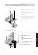
4. Within 2 s, turn rotary selector "tw"
to the top left range.
The display shows "
r
", "
w
", "
A
",
and the selected correction factor
flashes.
In the delivered condition, factor 0
has been set.
r
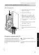
5. Within 15 s, set rotary selector
"
tr
" to the required correction fac-
tor.
6. The set correction factor is saved
when the value stops flashing, and
the control unit returns to standard
mode.
Correction factor 1 2 3 4 5 6
Flue system Rated
heating
output
(kW)
Max. run length (m)
Open flue operation 7 60 mm 19 4 10 16 22 — —
26/30 2 8 13.5 18.5 22 25
35 5 12 18 23 — —
Balanced flue operation
7
60/100 mm coaxial
19 2 6 10 13 16 19
26/30 1 4 7 10 12 13.5
35 3 6 9 12 14 17
Observe max. flue lengths. A calculated
performance verification is required if the
max. flue lengths in the table are excee-
ded.
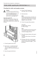
Reducing the max. heating output
The max. heating output can be reduced
according to the system requirements.
1. Turn ON/OFF switch ON.
Commissioning, inspection, maintenance
Further details regarding the individual steps
(cont.)
5609 059 GB