
Operating instructions

60
5603 882 - 01
Pyrotec Installation & Operating
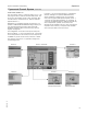
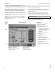
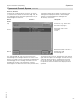
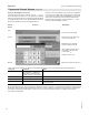
Pyrocontrol Control System (continued)
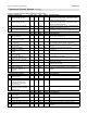
Pyrotec controller parameter reference guide for the technician (continued)
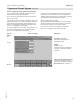
Fuel loading Unit Min. Max. Default Detailed definition
6 Extraction system direction of advance On/Off Off Changes direction of extraction system
7 Switch-on delay for hydraulic system Sec. 0 20 5 Walking floor switch on delay
8 Light barrier delay for hydraulic system Sec. 0 9.9 2.0 Walking floor switch off delay
9 Hydraulic system auger run time max. Sec. 20 999 80 Walking floor on time
10 Hydraulic drive emergency operation
jog
Sec. 10 999 90 Walking floor pulse time
11 Light barrier delay for auger after
in-feed auger 1
Sec. 0 9.9 0.5 Feed auger sensor off delay of walking
floor
12 Light barrier delay for auger after
in-feed auger 2
Sec. 0 9.9 0.5 Feed auger sensor off delay of walking floor
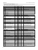
Regulator firing up Unit Min. Max. Default Detailed definition
1 Output controller, P-factor 0 99.9 5.0 Factor for how fast the boiler
heats up (output power),
DO NOT CHANGE SETTING
2 Output controller, D-factor 0 99.9 5.0 DO NOT CHANGE SETTING
3 Output controller, I-factor 0 99.9 0 DO NOT CHANGE SETTING
4 Fuel controller, P-factor 0 99.9 7.0 Factor for how fast material is fed into
the system (underfeed auger)
DO NOT CHANGE SETTING
5 Fuel controller, D-factor 0 99.9 5.0 DO NOT CHANGE SETTING
6 Fuel controller, I-factor 0 99.9 0 DO NOT CHANGE SETTING
7 Combustion chamber negative
pressure controller, P-factor (under
pressure of the combustion chamber
0 99.9 2.0 PID ramp up factor for how fast negative
pressure is controlled or adjusted.
(flue gas exhaust blower speed).
DO NOT CHANGE SETTING
8 Combustion chamber negative
pressure controller, D-factor
0 99.9 1.0 DO NOT CHANGE SETTING
9 Combustion chamber negative
pressure controller, I-factor
0 99.9 0 DO NOT CHANGE SETTING
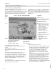
Internal settings Unit Min. Max. Default Detailed definition
1 External request from other system
such as primary boiler or outdoor reset
On/Off Off External start/stop input ONLY, to turn
boiler On or Off
2 External output specification from
external control system
On/Off Off External load regulation 0-10V DC input,
outdoor reset, controls output of boiler
3 Controller address, serial interface 0 999 110 Controller address, Not used only if
addition visualization is used
4 Enter permanent code 0 9999 Not used
5 Load Factory setting On/Off Off DO NOT CHANGE SETTING
6 Adjust oxygen sensor (lambda) On/Off Off Calibrate oxygen sensor if set to On *
7 Boiler forward flow temperature On/Off Off If set to Off uses return temperature
If set to On uses supply temperature
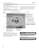
Accumulator management system Unit Min. Max. Default Detailed definition
1 Accumulator management system
operating mode
Auto/
Manual
/Off
Auto Controlled by accumulator system with
5 sensors
2 Accumulator management system
model
Kob/QM Kob Kob or other system
3 Accumulator monitoring in
accumulator sensor, selected sensor
B28.1
B28.5
B28.5 Sensor to be monitored in the thermal
storage tank for design temperature
4 Accumulator monitoring in
accumulator sensor, selected temp.
°C 30 120 85 Design temperature for the thermal
storage tank
Operation
* Auto reset, after calibration is complete.