
Operating instructions

27
5603 882 - 01
Pyrotec Installation & Operating
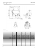
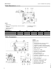
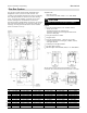
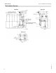
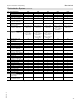
Mechanical
Safety Devices (continued)
B
C
D
F
G
H
J
K
L
M
O
P
E
I
A
R
Q
S
T
U
I
I
I
N
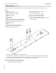
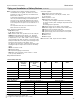
P Pressure relief valve, 30 psi or 60 psi
(KPT 1250, 30 psi only)
Q 4 in. or 6 in. Boiler supply flange
3
R Supply sensor well (sensor supplied)
S 4 in. or 6 in. Boiler return flange
3
T Return sensor well (sensor supplied)
U Sensor wells for thermal safety flush valve (Rb in.)
(sensor supplied)
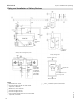
1 See section Piping and Installation of Safety Devices
2
Two PRVs must be installed on the KPT 1250 - 30 psi boiler. One PRV must be installed and the other PRV
connection must be capped on the KPT 1250 - 60 psi boiler. All other models have only one PRV connection.
3
4 in. boiler flange for Pyrotec 390-720, 6 in. boiler flange for Pyrotec 950-1250
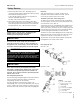
Legend
A Nipple, c in. x 1b in.
B Reducing coupling, c in. x b in.
C Boiler water temperature gauge
D Bushing c in. x a in.
E Nipple a in. x 2b in.
F Ball valve a in.
G Pressure gauge
H Sensor well - fixed high limit (sensor supplied)
I Safety heat exchanger connections, NPTM b in.
1
J PRV Pressure Relief Valve connection cap
2
K Reducing bushing
L Nipple
M Pressure relief valve, 30 psi or 60 psi
N Reducing bushing (KPT 1250, 30 psi only)
O Nipple (KPT 1250, 30 psi only)
Note: All fittings shown and sensors indicated are
factory supplied. The size and quantity are
matched to the specific boiler model.
The safety equipment for the heating installation must be installed by a heating contractor authorized to do so.