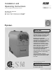
Installation and Operating Instructions for use by engineers and heating contractors KPT 390 to KPT 1250 Series Wood-fired Boiler Max. output: 390 to 1250 kW (1331 to 4266 MBH) Min. output: 98 to 370 kW (334 to 1263 MBH) Pyrotecr IMPORTANT Please ensure that these instructions are read and understood before commencing installation and start-up. Failure to comply with these Installation Instructions will render all warranties null and void.
Introduction Pyrotec Installation & Operating Safety, Installation and Warranty Requirements Please ensure that these instructions are read and understood before commencing installation and service. Failure to comply with the instructions listed below and details printed in this manual can cause product/property damage, severe personal injury, and/or loss of life. Ensure all requirements below are understood and fulfilled (including detailed information found in manual subsections).
Pyrotec Installation & Operating Introduction About These Instructions Take note of all symbols and notations intended to draw attention to potential hazards or important product information. These include ”WARNING”, ”CAUTION”, and ”IMPORTANT”. See below. WARNING Warnings draw your attention to the presence of potential hazards or important product information. CAUTION Cautions draw your attention to the presence of potential hazards or important product information.
Table of Contents Pyrotec Installation & Operating Page Introduction Safety, Installation and Warranty Requirements..............2 About These Instructions..............................................3 General Information Important Regulatory and Installation Requirements ........6 Codes...................................................................6 Mechanical room...................................................6 Working on the equipment......................................
Pyrotec Installation & Operating Mechanical (continued) Electrical 5603 882 - 01 Operation Table of Contents Page Fire Extinguishing System.........................................32 Assembly of the Fire Extinguishing System...................33 Negative Pressure Monitoring Assembly........................34 Control Panel...........................................................35 Mounting of control panel....................................35 Electrical connection.....................................
General Information Pyrotec Installation & Operating Important Regulatory and Installation Requirements Take note of all symbols and notations intended to draw attention to potential hazards or important product information. These include ”WARNING”, ”CAUTION”, and ”IMPORTANT”. Codes The installation of this unit shall be in accordance with local codes. In the absence of local codes, use: B 365-01, Installation Code for Solid-Fuel Burning Appliances and Equipment.
General Information Pyrotec Installation & Operating Product Information Viessmann solid-fuel boiler may only be installed and serviced by trained personnel. Steel wood-fired hot water heating boiler. For operation primarily with modulating boiler water temperatures in closed loop forced circulation hot water heating systems. Under certain conditions, open loop systems may also be considered. Contact Viessmann for details. Maximum allowable working pressure (water)...
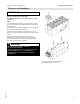
General Information Pyrotec Installation & Operating Boiler Description 8 Function: - The solid, powerful and heat-resistant in-feed auger moves the fuel over the burner trough into the descending and moving grate zone. An electrical and mechanical temperature sensor to operate the thermal extinguishing valve are located on the in-feed auger. Above the auger is the metering container with a light barrier for setting the level of the fuel insulating layer.
Pyrotec Installation & Operating General Information Transport and Installation IMPORTANT Precautions must be taken to avoid accidents and injury during the transportation of the boiler. Only hoist the boiler when it is entirely empty of water, fuel and ash. Lifting The combustion chamber has four lifting lugs that must be screwed in before lifting. Lifting gear can be attached to these lifting lugs. The pressure vessel of the PYROTEC has two lifting lugs to which lifting gear may be attached.
General Information Pyrotec Installation & Operating Delivery Condition Standard delivery condition The standard delivery condition of the Pyrotec boiler includes pre-assembled components as well as components that need to be assembled by the contractor in the field.
General Information Pyrotec Installation & Operating Wood Fuel Requirements The Pyrotec is only suitable for burning fuels listed in this section. A prerequisite for approval is of a fuel by Viessmann is the approval for the fuel by the responsible public authorities. Warranty claims for Viessmann Biomass boilers are excluded if the following fuel conditions are not met. IMPORTANT If different fuels are used, Viessmann will not assume any liability for the functioning or service life of the boiler plant.
General Information Wood Fuel Requirements Pyrotec Installation & Operating (continued) Maximum water content The maximum allowable water content of the fuel for Pyrotec systems is limited to 50%. The water content impacts the maximum boiler output. Non-wood fuels Non-wood fuels even if consisting of biomass, such as needles, foliage, grain, straw, fruit pits, etc, are unsuited as fuel for boiler operation and may not be used. Limitation super fines and dust [wood particles smaller than 1/32 in. (1.
General Information Pyrotec Installation & Operating Wood Fuel Requirements (continued) Content limits for non-combustible substances - No wood fuels may contain any foreign bodies, such as pieces of metal, stones, masonry remnants or plastics. The following limits (per lb/kg of dry fuel) of contained non-combustible substances apply [ash analyzed at a temperature of 1500° F (815° C)]: Substance Limit Comparative value untreated forest wood Chlorine (Cl) max.
Safety Pyrotec Installation & Operating Carbon Monoxide Therefore, carbon monoxide detectors that are in compliance with a nationally recognized standard (e.g. ANSI/UL 2034-2002, CSA 6.19-01) should be installed and maintained in buildings that contain woodburning equipment. Note: Viessmann does not test any detectors and makes no representation regarding any brand or type of detector. For safe operation We recommend that you frequently: - Check for debris which could obstruct the flow of flue gases.
Safety Pyrotec Installation & Operating Hazardous Materials Fiberglass wool and ceramic fiber materials WARNING Inhaling of fiberglass wool and/or ceramic fiber materials is a possible cancer hazard. These materials can also cause respiratory, skin and eye irritation. The state of California has listed the airborne fibers of these materials as a possible cancer hazard through inhalation. When handling these materials, special care must be applied.
Safety Pyrotec Installation & Operating Power Failure Provision Customers must ensure that there is a supply of water independent of the electrical supply. This design ensures that in case of a power failure, the boiler will be reliably cooled by the thermal safety flush valve. Venting Requirements The PYROTEC Grate Firing System is equipped with a flue gas exhaust blower. This boiler must be properly vented. Use a vent material certified for use with solid-fuel fired equipment.
Safety Pyrotec Installation & Operating Mechanical Room Ensure the mechanical room complies with the requirements in these instructions and local codes. Viessmann recommends the installation of an additional electrical disconnect switch and a fuel shut-off valve (if possible) outside the mechanical room or enclosed area of installation. A separate, dry heating room must always be provided for the PYROTEC Grate Firing System. No combustible materials may be stored in the heating room.
Safety (continued) WARNING Incorrect ambient conditions can lead to damage to the heating system and put safe operation at risk. Mechanical room conditions Prevent the air from becoming contaminated by homogenate hydrocarbons (e.g. as contained in paints solvents or cleaning fluids) and excessive dust (e.g. through grinding or polishing work). Combustion air for the heating process, and ventilation of the boiler room must be free of corrosive contaminants.
Pyrotec Installation & Operating Safety Combustion Air Supply Codes Provision for combustion and ventilation air must be made in accordance with applicable local codes. In the absence of local codes, use: CSA B365-10, Installation Code for Solid Fuel Burning Appliances and Equipment. Always use latest edition codes. WARNING Failure to provide an adequate supply of fresh combustion air can cause poisonous flue gases to enter living space.
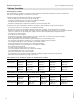
Mechanical Pyrotec Installation & Operating Technical Data 390 530 720 950 1250 Maximum output KPTMBH (kW) 1331 (390) 1808 (530) 2457 (720) 3242 (950) 4265 (1250) Minimum output1 MBH (kW) 334 (98) 450 (132) 614 (180) 812 (238) 1065 (312) Efficiency2 85% Fuel Moisture content3 % W 50 Size of wood chips4 G 30 / G 50 as per CAN/CSA-B366.
Mechanical Pyrotec Installation & Operating Specifications Boiler Dimensions BR BS BR Boiler Return BS Boiler Supply Dimensions 5603 882 - 01 Boiler Model KPT- 390 530 720 950 1250 (2834) 119½ (3035) 1271/8 (3230) a in. (mm) 93 b in. (mm) 915/8 (2328) 977/8 (2486) 1095/8 (2784) 1173/8 (2981) 125 (3176) c in. (mm) 172 (4370) 191¾ (4870) 207 (5257) 214½ (5447) 2357/8 (5992) d in. (mm) 87 100¾ (2560) 100 1223/8 (3107) e in.
Mechanical Boiler Dimensions Pyrotec Installation & Operating (continued) a b Legend A Boiler return B Motor for de-ashing assembly with ash container E Secondary air blower (optional) F In-feed auger C Primary air blower 1 D Boiler supply Dimensions Boiler Model KPT390 530 720 3/16 (3282) 5/8 (3877) 129 149 (3782) 152 a in. (mm) 1495/8 (3800) 1695/16 (4300) 1749/16 (4434) b in.
Mechanical Pyrotec Installation & Operating Flue Gas Cyclone The flue gas cyclone minimizes dust emissions and is designed as a multi cyclone with axial function. The cyclone is fully insulated and has three covers for cleaning. The crude gas chamber is cleaned via the side cleaning cover. The clean gas chamber is cleaned via the upper or back cleaning cover (unused blower connection). The ash box has a carriage and is connected to the cyclone with quick-action fasteners.
Mechanical Pyrotec Installation & Operating 24 5603 882 - 01 Recirculation System
Mechanical Pyrotec Installation & Operating Recirculation System (continued) Item no. 1 2 3 390 Quantity 1 1 5 530 Quantity 1 1 5 720 Quantity 1 1 5 950 Quantity 1 1 5 1250 Quantity 1 1 5 4 4 4 4 4 2 -- 1 -- -- 1[1x L=87/8 in. (225 mm)] 3[1x L=87/8 in. (225 mm)] 1[1x L=9 in. (228 mm)] 1[1x L=12d in. (308 mm)] 3[1x L=31c in. (805 mm)], 1[1x L=36 in. (914 mm)] 3[1x L=31c in. (805 mm)], 1[1x L=32f in. (830 mm)], 1[1x L=36 in. (915 mm)] 18 5[1x L=18d in. (460 mm)], 1[1x L=28e in.
Mechanical Pyrotec Installation & Operating Safety Devices 1. Install the pressure relief valve, discharge pipe, air vent and pressure gauge as illustrated in section piping and installation of safety devices. A 30 or 60 psi pressure relief valve is supplied with the boiler (standard equipment). The KPT 1250, 30 psi will have 2 PRVs. 2. Install a discharge pipe on the pressure relief valve. The end of the pipe must not be threaded.
Mechanical Pyrotec Installation & Operating Safety Devices (continued) The safety equipment for the heating installation must be installed by a heating contractor authorized to do so. Legend A Nipple, c in. x 1b in. B Reducing coupling, c in. x b in. C Boiler water temperature gauge D Bushing c in. x a in. E Nipple a in. x 2b in. F Ball valve a in. G Pressure gauge H Sensor well - fixed high limit (sensor supplied) I Safety heat exchanger connections, NPTM b in.
Mechanical Pyrotec Installation & Operating Piping and Installation of Safety Devices System fill Drain inspection port System fill Safety heat exchanger top view 3-Way mixing valve System return line Adjustment Blocked port 4 heat exchanger loops and 2 TS2430 for Pyrotec 720, 950 and 1250 Bypass line Valve adjustment must be facing forward Boiler return line 28 1, 2 and 3 indicates system connections 5603 882 - 01 Legend A Additional heat source B Thermal storage tank as low loss header (
Mechanical Pyrotec Installation & Operating Piping and Installation of Safety Devices Note: To reliably prevent boiler corrosion caused by condensation of flue gases, the boiler return flow temperature must not under any circumstances be below 150° F (65° C). A Viessmann sized boiler pump with a boiler mixing valve are provided according to the tables below.
Mechanical Pyrotec Installation & Operating Piping and Installation of Safety Devices (continued) Design Recommendation (continued): Boiler pump Boiler model KPT- Pump Frequency Voltage and phase 390 UPS 50-80/4 F 60 Hz 3 x 208-230 V 530 UPS 50-80/4 F 60 Hz 3 x 208-230 V 720 UPS 80-160 F 60 Hz 3 x 208-230 V 950 UPS 80-160 F 60 Hz 3 x 208-230 V 1250 TP 100-80/4 60 Hz 3 x 208-230 / 460 V Mixing valve Boiler model KPT390 530 720 950 1250 Viessmann ASME recommended tank sizes (U-sta
Mechanical Pyrotec Installation & Operating Fire Protection (continued) Back-burn safeguard for the fuel supply system The fire extinguishing system for the conveyor auger and the down pipe depends on specific requirements (location, size of the fuel storage site, material, pressure conditions and regulations), these being accessories to the scope of delivery ordered from Viessmann according to their descriptions.
Mechanical Pyrotec Installation & Operating Fire Extinguishing System The fire extinguishing system functions independent from the electrical power and is flooding the material which is still remaining in the in-feed auger in case of back-burn. The activation temperature is approximately 200° F (95° C) Fire extinguishing system for the conveyor auger Note: The fire extinguishing system for the conveyor auger is optional.
Mechanical Pyrotec Installation & Operating Assembly of the Fire Extinguishing System deburr drill hole 5603 882 - 01 Connection to the extinguishing water container or cold water supply piping (field supplied). Item No. Quantity Description Item No. Quantity 1 1 2 4 3 2 Hex nut M6 4 2 Threaded rod M6 5 2 Stud anchor e in. x 4a in. (10 mm x 108 mm) 6 1 Mounting bracket 7 1 Plastic container 6.6 USG (25 L) 8 2 Clamping band 9 1 Duct b in. 10 1 90° street elbow b in.
Mechanical Pyrotec Installation & Operating Assembly of the Fire Extinguishing System The following assembly instructions for the fire extinguishing system are to be used with the layout and description shown on page 31. - Install the mounting bracket (6) near the in-feed auger at a minimum height of 20 in. (500 mm) with the stud anchors (5) for wall mount. - Install the plastic container (7) to the mounting bracket (6) with the clamping bands (8), the threaded rods (4), washers (2) and the hex nuts (3).
Electrical Pyrotec Installation & Operating Control Panel Mounting of the control panel A certified electrician shall mount the control panel. Optimum positioning of the control panel will minimize the time and costs of the installation. The control panel should be in an area where the heat radiation (front side of boiler, rear side of boiler with flue gas cyclone and flue gas exhaust blower as well as recirculation line) and the exposure to dust during cleaning is at a minimum.
Electrical Pyrotec Installation & Operating Control Panel (continued) Vitocontrol - C, Pyrocontrol KPT Mains supply 208V, 3 phase, 60 Hz, see field wiring diagram for details.
Electrical Pyrotec Installation & Operating Control Panel (continued) Device tags and designations may vary from project to project. Please refer to the field wiring diagram for details. The wiring diagram will be supplied after the control panel is built or with the receipt of the control panel.
Electrical Pyrotec Installation & Operating 38 5603 882 - 01 Electrical Components
Electrical Pyrotec Installation & Operating Electrical Components M High voltage Y Low voltage High Voltage Number Designation 1 M1 2 M11 3 M13 4 M14 5 M15 6 M16 7 M20 5603 882 - 01 Low Voltage 8 9 10 11 12 13 14 15 16 17 18 19 20 Y20 Y71 Y72 Y73 Y74 Y75 Y76 Y77 Y78 Y79 Y80 Y81 Y82 (continued) B sensors S Switches Device tag -3M1 -9M11 -13M13 -14M14 -15M15 -16M16 -17M20 -18Y20 -20Y71 -20Y72 -20Y73 -20Y74 -20Y75 -20Y76 -20Y77 -20Y78 -20Y79 -20Y80 -20Y81 -20Y82 N Sensors Description Flue gas exhaust
Electrical Pyrotec Installation & Operating Fuel Transport and Extraction Systems Rotary Valve Designation Device tag A M9 -9 M9 Description Motor for rotary valve 5603 882 - 01 40 Number
Electrical Pyrotec Installation & Operating Fuel Transport and Extraction Systems (continued) In-feed auger Number 40 Designation Device tag Description M2 -4M2 Motor for in-feed auger 41 S2 -68S2 42 B31.1 -11B31.1 Light barrier metering container (Transmitter) Limit switch for maintenance lid 43 B31.2 -11B31.2 Light barrier metering container (Receiver) 44 M10.1 -8M10.1 Slide valve T30 45 M10.2 -8M10.
Electrical Pyrotec Installation & Operating Fuel Transport and Extraction Systems (continued) Pellet extraction auger Number Designation Device tag Description 51 M32 -12M32 Motor for pellet extraction auger 52 S32.1 -12S32.1 Limit switch for maintenance lid 53 S32.2 -12S32.2 Limit switch for silo door (not shown) Note: For details on designation see field wiring diagram. Spring extraction system Designation Device tag Description 54 M32 -12M32 55 S32.1 -12S32.
Electrical Pyrotec Installation & Operating Fuel Transport and Extraction Systems (continued) Horizontal extraction system Number Designation Device tag Description 57 M32 -12M32 Motor for extraction auger 58 M33 -12M33 Motor for agitator 59 B32 -12B32 Light barrier for extraction auger 60 S32.1 -12S32.1 Safety switch for maintenance lid 61 S32.2 -12S32.2 Safety switch for silo door (not shown) 5603 882 - 01 Note: For details on designation see field wiring diagram.
Electrical Pyrotec Installation & Operating Fuel Transport and Extraction Systems (continued) Walking floor auger Number 62 Designation M2 63 64 65 66 67 68 69 70 S3 S3.1 B3/1 B3/2 B6.1/1 B6.1/2 B6.2/1 B6.2/2 Device tag Description -4M2 Motor for walking floor auger -68S3 -68S3.1 -61B3/1 -61B3/2 -61B6.1/1 -61B6.1/2 -61B6.2/1 -61B6.
Electrical Pyrotec Installation & Operating Fuel Transport and Extraction Systems (continued) Silo Lid Number Designation Device tag Description 76 Y6.3 -22Y6.3 Solenoid valve silo lid open 77 Y6.4 -22Y6.4 Solenoid valve silo lid close 78 S6.1 -22S6.1 Key operated switch for silo lid 79 M901 -24M901 Vibration motor 1 80 M902 -24M902 Vibration motor 2 81 M903 -24M903 Vibration motor 3 82 S901 -24S901 Key operated switch for vibration motor 83 S5.1 -68S5.
Electrical Pyrotec Installation & Operating Boiler Wiring CAUTION The Viessmann supplied field wiring diagram is not a complete system drawing. It is the installer’s responsibility to assure that the control is suitable for the respective installation, and all necessary safety equipment is installed. CAUTION The information about wire type, wire number and wire gauge made in the wiring diagrams is not obligatory.
Operation Pyrotec Installation & Operating Commissioning Initial startup Only a Viessmann or another trained specialist may put a newly installed system into operation for the first time. Before the system is commissioned, the system must be filled with water, and the fuel for the commissioning and the installation itself must be inspected. Note: It is mandatory to complete the Viessmann biomass project pre-commissioning form. IMPORTANT Be absolutely sure to follow the instructions.
Operation Pyrotec Installation & Operating Filling the Fuel Storage Unit Horizontal extraction system and spring extraction system If any excess or negative pressure develops in the silo during the filling, the facility has to be switched off using the function button on the control panel. After doing so, complete filling the silo evenly and turn the facility back on, using the function button on the control panel. Carry out refilling in the same manner.
Pyrotec Installation & Operating Operation Excess Conditions Excess temperature/power failure CAUTION DANGER OF THIS EQUIPMENT SUDDENLY GOING UP IN FLAMES: DO NOT open the doors or lids on the boiler plant! - Switch on additional heat loads. The flue gas exhaust blower shuts down. The temperature-limiting safety switch triggers. The thermal safety flush valve opens at approx. 203° F (95° C). The excess heat is being dissipated into the drain.
Operation Pyrotec Installation & Operating Pyrocontrol Control System The control system for the Pyrotec boiler firing process (Pyrocontrol) is controlled by a Programmable Logic Controller (PLC), which visualizes the system on a touch screen and provides an interface for navigation and entering settings. The soft touch keys in Screen 1 Export of operational data via Mod-bus Pyrocontrol As an option, the Pyrocontrol boiler control unit can be extended with the Mod-bus (PYR-SED) extension module.
Operation Pyrotec Installation & Operating Pyrocontrol Control System (continued) Touch screen, Screen 1-8 The touch screen is 6¼ in. (160 mm) wide, 4¾ in. (120 mm) high and has a resolution of 640 x 480 pixels. The screen is a color display monitor. After switching “ON” the main switch, the PLC starts up, and the Overview appears (Screen 1). Navigation: The navigation program “Pyrocontrol” is a product of KÖB Viessmann Manufacturing Company Inc.
Operation Pyrotec Installation & Operating Pyrocontrol Control System (continued) The following applies to all screens. The screen title and user status are shown at the top. The screen title indicates which Screen (1-8) is active. The areas for display and call-up for entering settings are always located in the centre of the screen. The soft touch keys for navigation and input are located at the bottom, with the exception of the combined user status display and the call for input.
Operation Pyrotec Installation & Operating Pyrocontrol Control System (continued) Screen 2, Alarm list Touching the red Alarm line soft touch key (in Screen 1) opens Screen 2 (Alarm List with alarm logs, red). All error messages which have been registered but not yet acknowledged are listed here. Area of Screen Screen 2 Top Centre Bottom 5603 882 - 01 The “Acknowledge all” soft touch key (bottom left) acknowledges error messages listed in the centre of the Screen.
Operation Pyrotec Installation & Operating Pyrocontrol Control System (continued) Screen 3, Managing the user status Touching the soft touch key “Status Level 0”, …1, 2 or 4 (at the top right of the Screen), the user level can be changed and thus the access rights for entering settings stipulated. To change the user level, no user name needs to be entered, but all four possible levels are provided as buttons.
Operation Pyrotec Installation & Operating Pyrocontrol Control System (continued) Screen 4, Adjusting settings and process parameters In the Settings menu, adjustable categories can be chosen and their parameters changed. In the centre the parameters to be set are listed with their current values. If an attempt is made to change a parameter that is not cleared for change in the current user status, Screen 3 will be called up automatically.
Operation Pyrotec Installation & Operating Pyrocontrol Control System (continued) Screen 7, Overview, wood-powered boiler Touching the KÖB Boiler soft touch key (photo in Screen 1) opens Screen 7 (sectional view of the boiler). Here the most important process parameters, activity modes and operating hours are displayed. The operating mode display is located in the centre upper left of the screen.
Operation Pyrotec Installation & Operating Pyrocontrol Control System (continued) Screen 8, Additional boilers When the soft touch key for additional boilers is touched (symbol in Screen 1), Screen 8 opens (symbol for oil or gas boiler, enlarged). (For explanation on the text displays, see “Operating modes”). Here the supply flow and return flow temperature of the additional boiler is displayed. The KÖB Boiler operating mode display is located in the centre upper left of the screen.
Operation Pyrotec Installation & Operating Pyrocontrol Control System (continued) Pyrotec control system parameter Min. Max. Default Detailed definition 1 Boiler temperature, forward(out) flow °C 70 110 85.0 Set point for supply temperature, system design temperature 2 Boiler temperature, return(in) flow °C 65 95 70.0 Set point for return temperature 3 Residual oxygen, boiler % 4.0 15.0 8.
Operation Pyrotec Installation & Operating Pyrocontrol Control System (continued) Pyrotec controller parameter reference guide for the technician Regulator temperature Unit Min. Max. Default Detailed definition Hysteresis(lagging behind) °C 4 20 10.0 Value is calculated by value in 7 + value in 9, 9 standby (boiler off) ON puts boiler in standby mode, when boiler is On. DO NOT CHANGE SETTING °C 0 20 2.
Operation Pyrotec Installation & Operating (continued) Pyrotec controller parameter reference guide for the technician (continued) Fuel loading Unit Min. Max. Default 6 Extraction system direction of advance On/Off Off 7 Switch-on delay for hydraulic system Sec. 0 20 5 8 Light barrier delay for hydraulic system Sec. 0 9.9 2.0 9 Hydraulic system auger run time max. Sec. 20 999 80 10 Hydraulic drive emergency operation Sec. 10 999 90 jog 11 Light barrier delay for auger after Sec. 0 9.9 0.
Operation Pyrotec Installation & Operating Pyrocontrol Control System (continued) Pyrotec controller parameter reference guide for the technician (continued) Accumulator management system Min. Max. B28.1 B28.5 Default Detailed definition B28.1 Sensor used to start boiler when below value in 4 5 Starts boiler when temperature falls below selected sensor in acc 6 Accumulator set-point for atmospheric temp.
Operation Pyrotec Installation & Operating Operating Modes 62 Off The boiler is switched off. Filling Cold start. The combustion chamber trough is being filled by the underfeed auger. Auger filling Direct or hot start with combustion chamber still warm. The auger module is being filled. Igniting The igniter is running. The system is being started. Heating up The system is being slowly started. Full load The boiler is running in regular operation. Sustain Embers being sustained.
Operation Pyrotec Installation & Operating Operating Modes (continued) Full load operation As soon as a combustion chamber temperature of approximately 356° F (180° C) is reached (adjustable value), the system switches, depending on the boiler temperature, to operating mode “FULL LOAD” or “SUSTAIN”, which is shown in the upper left of the display. Output control The heat output to be produced is adapted to the heat consumption in a range from 25% to 100% of the boiler’s nominal output.
Pyrotec Installation & Operating Heating up Light a fire with paper and kindling wood in the combustion chamber. After this, use a shovel to push the fire back to the filled burner trough. Then press Soft touch key 1 “Boiler ON” again (Soft touch key 1 “Boiler ON” is then dark green). Operating mode “HEAT UP” shows in the upper left of the display. Fuel >W 40 - With fuel that has water content greater than W40, preheat the boiler with a chopped wood fire.