Operation and Maintenance Instructions PYROT 100 to 540 ID: 106811-H English
© by KÖB Holzfeuerungen GmbH Flotzbachstraße 33 A-6922 Wolfurt All rights reserved, including photomechanical reproduction and storage in electronic media.
1 General Information_________________________________________________ 4 1.1 1.2 1.3 1.4 1.5 1.
These Operating and Maintenance Instructions contain important information for the intended use, correct operation and proper maintenance of the PYROT. Any other use of the PYROT or use of it going beyond this will be considered as unintended use unless written approval by the manufacturer has been obtained. - Operation of the PYROT by unqualified personnel, without any training or knowledge of the Operating and Maintenance Instructions. - Disabling the safety or monitoring devices on the PYROT.
2.2 Excess temperature/power failure 2 Important Information 2.1 Safety instructions CAUTION DANGER OF THIS SUDDENLY GOING UP IN FLAMES: Do not open the doors or lids on the boiler plant! When carrying out work on the heating system, such as cleaning and maintenance, wear appropriate protective equipping when required. There is a danger of getting injured through: burning, knocking against corners and edges, crushing in moving parts and noise.
2.4 A fire hazard With insertion-type firing systems, the conveying route creates a connection between the silo and the burning material in the boiler plant. With the PYROT insertion-type heating boiler, the feed auger is also the metering auger, and is thus always filled up with material during operation There are various safety devices provided to prevent burn-back.
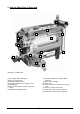
3 How the Boiler Plant is Strucured 12 11 9 14 10 8 7 4 3 5 13 4 6 2 1 (Illustration: PYROT 300) (1) Feed auger with isolating layer (2) Drive for moving grate (3) Automatic ignition device (4) Controlled combustion air supply system (5) Moving grate (6) Drive for automatic de-ashing system (optional) (7) Rotation fan (KÖB-patented) (8) Rotation combustion chamber (KÖBpatented) (9) Boiler heat exchanger (10) Boiler door (11) Heat exchanger for thermal run-off safety valve (12) Speed-controlled
4 Commissioning/Operation 4.1 The initial start-up The initial start-up is carried out either by KÖB Holzfeuerungen GmbH or a competent individual named by it. - When the "System Temperature Setting" is fallen short of, the facility is automatically started back up. 4.2.3 Switching off Be absolutely sure to follow the instructions in the Assembly and Installation Instructions. No guarantee may be claimed for damages in cases of initial start-ups carried out improperly at one's own initiative.
5 Oil burners on a Pyrot Be sure to note: - - - The oil burner's firing power may amount to a maximum of 70% of the rated heat output in wood-burning operation. The selection of the oil burner as well as the actual nozzle length have to be determined by the supplier of the oil burner. Only either wood-burning operation or oilburning operation is possible. For wood-burning operation, put in the sealing plug. Close the flue gas recirculation system.
F3 (PYROT Parameters) Setting parameters, set point values, the date and time 6 The ECOTRONIC control system F4 (PYROT Loader System) Setting of cycle switchover switching, advanceflow and post-flow times F5 (Group 1) Setting parameters and set point values (heat distribution, Group 1) F6 (Group 2) Setting parameters and set point values (heat distribution, Group 2) F7 (Group 3) Setting parameters and set point values (heat distribution, Group 3) 6.
6.3 Boiler and loader system (F3/F4) (16) Storage Unit Management, Temperature, Storage Unit Average (80°C): Set point value, average temperature, storage unit Æ boiler output is reduced according to loading of storage unit. (Indication only for storage unit option) 6.3.
6.3.2 The F4 KEY: "PYROT Loader System" (mask number) parameter (factory setting) (01) Cleaning (NO): This activates the cleaning function. Exhaust fan at starting speed, and moving grate on. (05) Moving grate, pause (60 s): Cycle switching for the moving grate (adjustable pause time, impulse fixed, 2 seconds).
6.4 Extended control systems F5 – F8 (optional) The F5 to F8 keys are assigned customer-specific extended control systems as desired. Each extended control system is assigned a separate key. (04) Heating Period 1/Start (6:00) Time to switch from lowered temperature (or off) to normal temperature. (05) Heating Period 1/End (22:00) Time to switch from normal temperature (or off) to lowered temperature. 6.4.
The heating curve Room thermostat (ECO-ZR-QA): The correspondence of the flow temperature to the outdoor temperature can be set directly and read directly. The setting is carried out by two points: Point 1: Flow temperature at atmospheric temperature of +5°C (setting range from 20°C to 90°C). Point 2: Flow temperature at atmospheric temperature of 15°C (setting range from 20°C to 90°C). The Model QAA 35 Room Thermostat can be used with or without influence by the room temperature.
6.4.2 Utility water heater (mask number) parameter (factory setting) Function: - - ECO-B1 When the temperature of the utility water drops, it is reheated by the built-in heat exchanger from the heat accumulator (hydraulic switcher). The condition for this is a relevant difference in temperature (choice of control according to temperature difference or fixed temperature). The heating periods (daily and weekly programmes) can be set using the integrated timer.
6.4.3 Air heater Function (ECO-L): (05) Heating Period 1/End (22:00) Time to switch off air heater. The air heaters are supplied at maximum flow temperature from the boiler plant storage system. The fans are connected by switches or controllers provided by the customer. The flow rate of the heating water is controlled by the temperature of the return flow and thus adjusted to the air heater's thermal output (quantity control).
6.4.4 Annex buildings Function (ECO-N): (04) Heating Period 1/Start (6:00) Time to switch from lowered temperature (or off) to normal temperature. The pipeline is usually supplied with a lowered temperature required by the weather-guided heating control system. The utility water heater is loaded at the maximum flow temperature set. To do so, the heating water is re-channelled by a valve to the utility water heater.
The heating curve 6.4.5 Pipelining See "Extended control system for room heating unit" Room thermostat (ECO-ZR-QA): Function (ECO-F): This is for an annex building with a separate heat distribution system, which is supplied with heat via a pipeline. According to prompts by the heat distribution system, the temperature of the pipeline is pre-adjusted for the lowest loss in the line.
6.4.6 Additional heat generator Function (ECO-KP1): (10) Load storage unit to (70°C): To what temperature on the accumulator sensor selected should the additional heat generator heat up the accumulator? (Indication only with accumulator option) The additional heat generator is automatically connected when required. This takes place after the system temperature is fallen short of that is set for covering the entire heat requirement or a peak in heat requirement.
6.4.7 Solar Function (ECO-S1): Operating modes This is used in simple solar systems with a single control circuit to heat the utility water in the solar utility water heater (Art. No: WSS-___). The ECO-S1 controller is an additional component for the ECO-B1(2) controller for the utility water heater. When the solar collector is hotter than the utility water at the bottom, it is heated up by the solar collector. - - Operating modes - Off: Pump off; valve shut.
7 Cleaning/Maintenance 7.1 Boiler Regular cleaning and maintenance of the facility is the customer's most important job for years of trouble-free operation and to obtain the greatest possible output with the best efficiency. Here the cleaning intervals for chip material are listed as per ÖNORM M 7133 with clinging bark – 0.8% ash content. The cleaning intervals may vary, depending on the fuel, the amount of fine matter and the operating method.
Pneumatic tube-cleaning system (optional) Exhaust gas deduster, detached (optional) After approx. 1000 operating hours: Unplug the plug, unscrew butterfly nuts, pull out motor with impeller and clean with broom or wire brush. CAUTION: DANGER OF INJURY – be absolutely sure to switch off master switch. After each cleaning of the set of tubing Open lid and clean the guide blades of the de-duster with hand-brush. Regularly drain condensation water in the compressed air distribution bar. After approx.
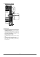
7.1 Installing the displacement rods into the heat exchanger The displacement rods improve the heat transmission in the heat exchanger and reduce the temperature of the exhaust gas, thus improving the efficiency of the heating system. They are taken out to clean the heat exchanger tubes and then put back in. Insert the displacement rods into the heat exchanger tube with the thick end first. Push until they are flush with the bottom of the tube. Tolerance +/- 5 mm. Fig.
Why? - The "intermittent control system" switches the consumer pumps on for five seconds every 24 hours. This prevents the pumps from jamming during long standstills. This saves on expensive repairs. - Prevent the formation of condensation in the lambda sensor. - Extend the service life of the buffer battery. 7.2 Feed systems All the geared motors on the feed systems are maintenance-free. - - - - A change of lubricant and/or oil is recommended every 20,000 operating hours or every three years.
Spec Sheet Wood Fuels Minimum Requirements / Information 1010/d-1 2007-09-12_E A prerequisite for approval is the express permission for such by the public authority responsible. For claims to the warranty according to Section 11 of our General Terms and Conditions of Delivery, wood fuels have to meet the following conditions.
Spec Sheet Wood Fuels Minimum Requirements / Information 1010/d-2 2007-09-12_E 4.2) Chips not from the forest; origin as per 3.2, 3.3, 3.4; briquettes, origin as per 3.3 Size essentially as per ÖNORM M 7133 G50, additionally, however: - Fraction of one-offs max. 5% with cross-section of max. 5 cm² up to a length of max. 16 cm - Frayed surface by chopping tools (shredders) or slow-running choppers - Briquettes, diameter max.
Excess temperature (F1, F2, F3 lights up red) Text displayed for malfunction 26 Pyrot ECO 2005-05-01_E BUS error, no connection to 81-93 the . . . (F3 lights up red) Feed auger pipe too hot Light barrier, feed auger (F3 lights up red) 25 96 Light barrier, ember monitoring system (F3 lights up red) 20 - Viewing windows soiled; deposits of ash in the openings - Defective malfunction alarm.
Text displayed for malfunction Pyrot ECO 2005-05-01_E Interruption or short-circuit, 01-27 sensor . . . (F… lights up red) No. 53-54 53-54 51-52 31-45 30 - Sensor . . .
Leerseite für Notizen: Blank page for notes: Page en blanc pour des notationes:
Leerseite für Notizen: Blank page for notes: Page en blanc pour des notationes:
Leerseite für Notizen: Blank page for notes: Page en blanc pour des notationes:
KÖB Holzfeuerungen GmbH, Flotzbachstrasse 33, A-6922 Wolfurt Tel +43 55 74 / 67 70-0, Fax +43 55 74 / 65 7 07 office@kob.cc, www.koeb-holzfeuerungen.com Viessmann Group Verkaufs-Niederlassungen und dazugehörige Service-Außenstellen: ZENTRALE: 1 Flotzbachstrasse 33, A-6922 Wolfurt ÖSTERREICH – NORD / OST 1 A-4906 Eberschwang Tel +43 55 74 / 67 70-0 Fax +43 55 74 / 65 7 07 office@kob.cc 1 VERTRIEBSTOCHTER SCHWEIZ KÖB Wärmetechnik AG CH-9430 St.