
Installation Guide

Viega IM-PFMB 1007
17
s
o as not to induce bending
stress on the MANABLOC.
Necessary elbows, couplings,
and tees are allowed in the main
water supply lines.
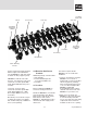
16. Reattach the MANABLOC to the
mounting straps.
When the MANABLOC is
installed prior to wall finishing
operations, the unit MUST be
protected from paint, texture
compounds and drywall dust.
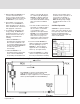
NOTE: The wall in which the
MANABLOC is to be mounted must
be accessible from both sides during
installation to use the MBB2
Mounting Straps.
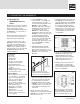
5.2 Mounting The
MANABLOC Without
Use Of MBB2 Straps
If not using the MBB2 Mounting
Straps, this procedure applies:
1. Cut two pieces of lumber (1 x 4 - or
3/4" plywood - about 3-1/2" wide) to
a length which provides a snug fit
BETWEEN two studs.
2. The top of the MANABLOC should
be between 4 ft. and 6 ft. from the
floor (but may be at any height
provided that it maintains
accessibility to all of the ports on
the MANABLOC).
Make a mark near the back of the
inside of one stud which would
represent the top of the
MANABLOC.
With a framing square or level,
transfer the mark to the inside back
of the other stud.
a thickness of 1-1/2" and about
3-1/2" wide on the left and right
sides of the mounting base and
r
unning the full-length of the
MANABLOC (see illustration,
step 4.5). The 2 x 4s will be used to
secure the distribution lines at the
correct height as they exit the
MANABLOC.
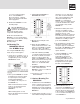
3. Attach the mounting base to the
structure in a suitable location
(see page 4). The base should be
mounted so the top of the
MANABLOC is between 4 feet and
6 feet from the floor but may be at
any height provided that the height
maintains accessibility to all the
ports on the MANABLOC.
4. The mounting base must be firmly
attached to a structure solid
enough to support, at a minimum,
the weight of the MANABLOC filled
with water. The base should be
square and level.
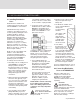
5. Center the MANABLOC on the
base both vertically and
horizontally as shown here.
Attach the MANABLOC to the
mounting base with four 1/2" or
longer drywall or wood screws
through the holes in the plastic
brackets on the MANABLOC.
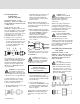
6. As the distribution lines are
connected to the MANABLOC (see
section 6), ensure that the tubing
exits the unit at a 90 degree angle
to the centerline of the MANABLOC
so as not to induce bending stress
on the MANABLOC.
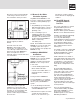
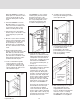
3
. ATTACHING THE MANABLOC
BETWEEN THE STUDS:
A. Measure the total length of the
MANABLOC.
B. Attach the first (UPPER) 1 x 4
inside and flush to the back of the
studs (see TOP VIEW) at a height
where the center of its width is
centered on the marks from step 2.
C. Attach the remaining (LOWER)
1 x 4 inside and flush to the back of
the studs at a distance below the
upper 1 x 4 that is equal to the
length of the MANABLOC (step 7A)
when measured from the top of the
upper 1 x 4 to the bottom of the
lower 1 x 4. See FRONT VIEW
illustration.
4. CENTER THE MANABLOC IN THE
STUD CAVITY: Attach the
MANABLOC to the 1 x 4s with four
1/2" - 3/4" drywall.
5. Refer back to section 5, step 5.1 to
finish installation.
5.3 Surface Mounting The
MANABLOC
1. A suitable base for the MANABLOC
can be constructed from a section
of 1/2" or thicker plywood that is a
minimum 22-1/2" wide and slightly
longer than the overall length of the
MANABLOC.
2. Securely attach a length of 2 x 4, or
other suitable framing material with