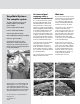
Viega ProPress System Installation Manual The global leader in plumbing, heating and pipe joining systems
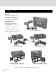
iega Metal Systems: V The complete system This guide is designed to provide you with installation guidelines for Viega Metallic Systems including: ProPress® Copper and Bronze fittings ProPress® Stainless pipe and fittings Seapress Copper-Nickel-Iron fittings Sanpress INOX Stainless Metric pipe and fittings ProfiPress Copper metric fittings System function and safety can only be guaranteed as a complete system if Viega components are used exclusively.
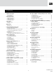
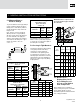
CONTENTS 1 System Description 10 Seapress (Metric Cu-Ni-Fe) Fittings 15 mm – 108 mm 1.1 Viega Metal Systems . . . . . . . . . . . . . . . . . . . . . . . . . . . . . . . . . . . . . . . . . 4 1.2 Special Features. . . . . . . . . . . . . . . . . . . . . . . . . . . . . . . . . . . . . . . . . . . . . 4 10.1 10.2 10.3 10.4 10.5 10.6 10.7 2 Seals and Gaskets 2.1 2.2 2.3 2.4 EPDM Sealing Element. . . . . . . . . . . . . . . . . . . . . . . . . . . . . . . . . . . . .
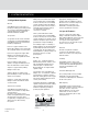
1. SYSTEM DESCRIPTION 1.1 Viega Metal Systems General Viega Metal Systems is the state-ofthe-art press fitting system that provides an economical and reliable installation of metal tubing for the commercial, industrial and marine markets. The Systems Our products are the result of decades of experience in manufacturing fittings. Viega Metal Systems are offered in the following configurations: ProPress: Copper and Zero Lead Bronze Alloy fittings in inch copper tube size (CTS) with Smart Connect® feature.
World’s Largest Selection of Fittings There are more than 3,000 different engineered fittings available in a variety of materials, configurations and sizes. Professional Appearance Because there is no buildup of joining material, exposed threads, or tarnish, Viega Metal System connections have a clean, professional look. Less Equipment With Viega Metal Systems there is no need to buy or carry expensive cumbersome equipment. Welding tanks and threading machines are a thing of the past.
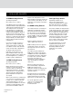
2. SEALS AND GASKETS 2.1 EPDM Sealing Element Operating temperature: 0°F to 250°F (-18°C to 120°C) Viega Metal Systems press fittings are manufactured with a high-quality EPDM sealing element installed at the factory. This sealing element is used mainly in the applications of potable water, hydronic heating, fire sprinkler and compressed air installations. EPDM, or ethylene-propylene dienemonomer, is shiny black in color.
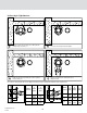
3. SMART CONNECT FEATURE 3.1 Viega Smart Connect Feature In ProPress 1/2" to 4" dimensions, the Smart Connect® feature (Fig. 3.1) assures leakage of liquids and/or gases from inside the system past the sealing element of an UNPRESSED connection. The function of this feature is to provide the installer quick and easy identificaiton of connections that have not been pressed prior to putting the system into operation (Fig. 3.3). 3.
4. PRESS TOOLS 4.1 Tools Viega recommends RIDGID press tools, ProPress jaws and ring sets manufactured and sold by RIDGID Tool Company for Viega Systems. ® ® 4.
5. GENERAL INSTALLATION INSTRUCTIONS 5.1 Minimum Distance Between Fittings Minimum distance between two Viega ProPress XL® press connections 2-1/2" to 4" To prevent distortion of the pipe, fittings require a minimum distance between fittings (refer to chart below). Failure to provide this distance may result in an improper seal. Note: ProPress systems include XL (Bronze) and XL-C (Copper) fittings. All other systems denote XL fittings as the same material as the piping (i.e.
V2 Pressing in Tight Quarters 1 3 Wrap the actuator ring around the press fitting with the opening facing away from you. 2 Close the actuator right around the fitting. Rotate the actuator ring until the press jaw receptacle is facing towards you. 4 Properly insert press jaws and begin the press fitting procedure. Procedure for the laying the XL-C Press Ring around the XL-C press fitting with minimum space requirements.
R2 Pressing in Tight Quarters 1 3 Wrap the actuator ring around the press fitting with the opening facing away from you. 2 Close the actuator right around the fitting. Rotate the actuator ring until the press jaw receptacle is facing towards you. 4 Properly insert press jaws and begin the press fitting procedure. Procedure for the laying the XL Press Ring around the XL press fitting with minimum space requirements.
5.4 Transition Connections Threaded Connections amin The Viega Metal Systems 1/2" – 4" can be joined with off-the-shelf threaded fittings (thread in accordance with DIN 2999) or armatures made of non-ferrous metals. In this regard: j The threaded connection is made first. k The press fitting is made. This process avoids unnecessary torsion. Flange Connections When using Viega flanges, bolt the flange end in place prior to pressing the fitting to the tubing. 5.
6. AREAS OF APPLICATION 6.1 Commercial and Residential The ProPress System is approved for applications in the commercial and residential market. The ProPress system is approved for potable water applications. "Zero Lead" identifies Viega products meeting the lead free requirements of California and Vermont law, effective January 1, 2010, as tested and listed against NSF- 61, Annex G. For additional applications please refer to the approved application chart or consult your local Viega District Manager. 6.
7. PROPRESS COPPER FITTINGS 1/2"- 4" 7.1 Tube Selection • Viega ProPress copper and bronze • fittings are compatible with 1/2" – 1-1/4" soft copper tube and 1/2" – 4" hard copper tubing type K, L, and M copper tubing. All copper tubing that is to be used with the ProPress copper and bronze fittings must comply with ASTM B88 standards. Minimum Distance 7.2 Handling Instructions Like Figure 5.
7.8 Codes and Approvals NSF International Annex G IAPMO 3. Check seal for correct fit. Do not use oils or lubricants. Use only ProPress shiny black EPDM or dull black FKM sealing elements. 7. Open the jaw and place at right angles on the fitting. Visually check insertion depth using mark on tubing. UL ICC ABS (American Bureau of Shipping) CSA International FM Compliant with: 4. While turning slightly, slide press fitting onto tubing to the fitting stop. End of tubing must contact stop. 8.
7.10 ProPress XL® Installation Read, understand and follow all instructions for installing ProPress XL fittings. Failure to follow all instructions may result in extensive property damage, serious injury or death. 9. With Actuator inserted into the tool, open the Actuator as shown. ProPress XL Insertion Depth Chart Tube Size 2-1/2" 3" 4" Insertion Depth 2-1/8" 2-1/8" 2-1/2" 5. Check seal and grip ring for correct fit. Note: Tubing shall be free of surface imperfections. 1.
7.11 Zero Lead* ProPress XL-C Read, understand and follow all instructions for installing ProPress XL-C fittings. Failure to follow all instructions may result in extensive property damage, serious injury, or death. Note: Tubing shall be free of surface imperfections. ProPress XL-C Insertion Depth Chart Tube Size 2-1/2" 3" 4" Insertion Depth 1-5/8" 1-7/8" 2-3/8" 10. With V2 ACTUATOR inserted into the tool, open the V2 ACTUATOR as shown and connect V2 ACTUATOR to the XL-C Ring. 5.
8. PROPRESS STAINLESS PIPE AND FITTINGS 1/2" - 4" 8.1 Viega Press Systems Pipes Identification These include: Only Viega ProPress Stainless piping is approved for installation with ProPress Stainless. This is to ensure reliability and conformity with the stainless steel system. ProPress Stainless pipe comes in sizes 1/2" – 4".
8.6 ProPress Stainless 1/2" - 2" Installation 5. Mark insertion depth. 9. After pressing, the jaw can be opened again. Read, understand and follow all instructions for installing ProPress fittings. Failure to follow all instructions may result in extensive property damage, serious injury, or death. Note: Tubing shall be free of surface imperfections. 1. Cut stainless steel piping at right angles using displacement type cutter or fine-toothed steel saw.
3. Remove burr from inside and outside of piping to prevent cutting sealing element. 7. Propress Stainless fitting connections must be performed with ProPress XL-C Rings and V2 ACTUATOR. Use of ProPress XL Rings and/ or Actuator (for Bronze fittings) will result in an improper connection. See RIDGID® Operator’s Manual for proper tool instructions. 10. Place V2 ACTUATOR onto XL-C Ring and start pressing process. Hold the trigger until the Actuator has engaged the XL-C Ring.
9. PROFIPRESS (METRIC COPPER) 15 MM – 108 MM 9.1 Tube Selection 9.4 Rotating a Pressed Fitting Viega ProfiPress copper and bronze fittings are compatible with metric 15 mm through 22 mm soft copper tube and 15 mm through 108 mm hard copper tubing type K, L and M copper tubing. Once a ProfiPress fitting has been pressed it can be rotated (not by hand), but once rotated more than five degrees, the fitting must be re-pressed to restore the resistance to rotational movement.
7. Open the jaw and place at right angles on the fitting. Visually check insertion depth using mark on tubing. 8. Start pressing process and hold the trigger until the jaw has engaged the fitting. 9. After pressing, the jaw can be opened again. 10. For applications requiring ProPress with FKM sealing elements, remove the factory installed EPDM sealing element and replace with FKM sealing element. 1. Cut copper tubing at right angles using displacement type cutter or fine-toothed steel saw. 2.
9. With V2 ACTUATOR inserted into the tool, open the V2 ACTUATOR as shown and connect V2 ACTUATOR to the XL-C Ring. 10. Place V2 ACTUATOR onto XL-C Ring and start pressing process. Hold the trigger until the Actuator has engaged the XL-C Ring. Keep extremities and foreign objects away from XL-C Ring and V2 ACTUATOR during pressing operation to prevent injury or incomplete press. 11. Release V2 ACTUATOR from XL-C Ring and then remove the XL-C Ring from the fitting on completion of press.
10. SEAPRESS (METRIC Cu-Ni-Fe) FITTINGS 15 MM – 108 MM 10.1 Tube Selection 10.4 Rotated a Pressed Fitting Viega Seapress fittings are compatible 15mm through 108mm metric seamless drawn tubes consisting of a corrosion resistant copper-nickel wrought alloy material. Once a Seapress fitting has been pressed it can be rotated (not by hand), but once rotated more than five degrees, the fitting must be re-pressed to restore the resistance to rotational movement.
7. Open the jaw and place at right angles on the fitting. Visually check insertion depth using mark on tubing. 8. Start pressing process and hold the trigger until the jaw has engaged the fitting. 1. Cut tubing at right angles using displacement type cutter or finetoothed steel saw. 5. Check seal and grip ring for correct fit. Use only ProPress shiny black EPDM sealing elements. 2.
9. Open XL Ring and place at right angles on the fitting. XL Ring must be engaged on the fitting bead. Check insertion depth. 10. With V2 ACTUATOR inserted into the tool, open the V2 ACTUATOR as shown and connect V2 ACTUATOR to the XL Ring. 11. Place V2 ACTUATOR onto XL Ring and start pressing process. Hold the trigger until the Actuator has engaged the XL Ring. Keep extremities and foreign objects away from XLRing and V2 ACTUATOR during pressing operation to prevent injury or incomplete press. 12.
11. SANPRESS INOX (STAINLESS METRIC) PIPE AND FITTINGS 15 MM -108 MM 11.1 Viega Press Systems Pipe Only Viega Sanpress INOX piping is approved for installation with Sanpress INOX fittings. This is to ensure reliability and conformity with the stainless steel system. Sanpress INOX pipe comes in sizes 15mm through 108mm.
2. Debur piping on inside and outside to prevent cutting fitting seal. 6. Insert the appropriate jaw into the pressing tool and push in holding pin until it locks into place. 11.7 Sanpress INOX 76 mm – 108 mm Installation Read, understand and follow all instructions for installing Sanpress fittings. Failure to follow all instructions may result in extensive property damage, serious injury, or death. 3. Check seal for correct fit. Do not use oils or lubricants.
4. Mark proper insertion depth as indicated by the Sanpress INOX insertion depth chart. Improper insertion depth may result in an improper seal. 7. Sanpres INOX fitting connections must be performed with ProPress XL Rings and V2 ACTUATOR. Use of ProPress XL Rings and/or Actuator (for Bronze fittings) will result in an improper connection. See RIDGID® Operator’s Manual for proper tool instructions. 11. Release V2 ACTUATOR from XL Ring and then remove the XL Ring from the fitting on completion of press.
12. PROPRESSG™ 12.1 Welcome 12.2 Intent 12.3 History By choosing to install a CSA LC-4 This publication is intended to provide information and guidance to design and installation professionals with regards to copper tubing systems using ProPressG fittings for fuel oil, natural gas, liquid propane gas and fuel oil piping systems.
13. SYSTEM DESCRIPTION 13.1 System Description ProPressG is a copper press connection system designed to meet the demands of natural gas and liquid propane gas in the vapor state, as well as fuel oil systems. Press fittings are manufactured in copper and bronze and fittings with NPT connections are manufactured in bronze. ProPressG fittings use an HNBR sealing element to provide permanent leak-proof connections in dimensions from 1/2" to 2". All fittings have a built-in Smart Connect Feature.
14. PROPRESSG APPLICATIONS 14.1 Fuel Gas Systems All ProPressG fittings have a factory installed HNBR sealing element that can be installed in ambient temperature ranges from -40°F (-40°C) to 180°F (82°C) and a maximum operating pressure of 125 psi (8.6 bar), making them suitable for many applications. ProPressG fittings are approved for installations in above and below ground applications.
15. PRODUCT DESCRIPTION 15.1 Fittings Viega ProPressG Fittings are currently offered in more than 120 fitting configurations. ProPressG fittings are manufactured in copper and bronze and are available in sizes ranging from 1/2"to 2". Every fitting is provided with a factory installed HNBR sealing element. In addition, all fittings include our patented Smart Connect feature.
Designers and installers should be specific with size designations in their references and when ordering. Copper and copper alloy tube should not be used if the gas contains more than an average of 0.3 grains of hydrogen sulfide per 100 standard cubic feet (scf) of gas (0.7 mg/100 L). Today, federal regulations limit the amount of hydrogen sulfide allowed in natural gas transmission.
1/2 - 85 psi. The Smart Connect feature test is not a substitute for local code required pressure testing. The final pressure test is to be carried out in Figure 15.3: Cross-section through a ProPressG connection after pressing Figure 15.1: Smart Connect feature in ProPressG 1/2" to 2" fittings. accordance with local codes. 15.5 Press Connections The pressing process provides a simple, safe and reliable means of connecting copper tubing for fuel gas systems with ProPressG fittings as shown in figure 15.
Viega IM-MTL 0612 724607 36
Viega IM-MTL 0612 724607
Viega IM-MTL 0612 724607 38
Viega IM-MTL 0612 724607
Viega IM-MTL 0612 724607 40
Viega IM-MTL 0612 724607
Viega IM-MTL 0612 724607 42
Viega IM-MTL 0612 724607
Viega IM-MTL 0612 724607 44
Viega IM-MTL 0612 724607
16. INSTALLATION REQUIREMENTS 16.1 Clearance Requirements Minimum clearance requirements for the pressing process Table 16.2: Space requirements for press jaws between pipe and wall/ floor structure c The minimum clearance required between two tubes and between the tubing and any permanent structure must be taken into consideration. The minimum allowable values are specified in Tables 16.1 and 16.2.
diagonal to the joists may be installed through holes drilled through the center of the joists. These holes must be a minimum of 1-1/2 times the O.D. of the tubing. See Table 16.5 for more information. This is to permit the movement of the appliance. When connecting a copper tubing fuel gas piping system to a steel pipe, cast bronze ProPressG fittings must be used. These bronze fittings provide protection from galvanic action. 16.
movement of the tubing. However, all systems must be installed per local code requirements. ≥ 4" of the tubing. All parts of the support equipment need to be designed and installed, not to disengage by movement of the supported tubing. Sliding hangers must be positioned so that they cannot unintentionally become rigid hangers when the system is in use. Fig. 16.3 shows a sliding tubing hanger that becomes a rigid hanger with spacing in excess of 10". Table 16.6: Hanger Spacing Tube Nominal Tube Copper Max.
Specific identification must meet the requirements of the applicable local codes. Each system, however, must be clearly marked with appropriate labels to identify that it is a gas system, the type of the system (low pressure, elevated pressure) and for elevated pressure systems, the system delivery pressure. The low pressure system can use the label shown in Figure 16.7 while the high pressure system can use markings similar to that shown in Figure 16.8.
16.12 Installation Instructions For Types K or L Hard Copper Tubing in 1/2" to 2" and Soft Copper Tubing in 1/2" to 1-1/4". Read and understand all instructions for installing ProPress fittings. Failure to follow all instructions may result in extensive property damage, serious injury, or death. 1 2 3 4 6 6a 7 8 5 9 Note: Tubing shall be free of surface imperfections. 1. Cut copper tubing at right angles (using displacement type cutter or fine-toothed steel saw. 2.
17. SYSTEM DESIGN AND SIZING 17.1 System Design ProPressG fittings and copper tubing may be used in any fuel gas piping systems where the quality of the fuel gas has less than or equal to 0.3 grains of hydrogen sulfide per 100 standard cubic feet of gas (0.7 milligrams per 100 liters). Information regarding fuel gas quality may be obtained from the local gas supplier. For natural gas, contact the local gas utility. For liquid propane gas, contact the liquid propane gas supplier.
brace or bracket and run copper tube through to the outside allowing service personnel to be aware that it is a semi-rigid system and damage can be avoided. The connection between the steel system and copper system does not create a corrosion concern if the connection is made in a dry location or a location that does not allow moisture to collect at the connection. The absence of continuous moisture prevents the occurrence of galvanic action and subsequent corrosion of the steel pipe.
The main runs of piping are still sized based on the longest length and total load method. Each branch can then be individually sized. The length of piping to apply when using the table is the length of piping from the point of delivery to the most remote appliance in the branch including both horizontal and vertical piping. Grill Range Dryer Gas Meter Shut-off Valve Furnace Water Heater Fireplace Figure 17.
Table 17.1 Copper Tubing Gas Natural Inlet Pressure 0.5 PSI or less Pressure Drop 0.3 inch WC Specific Gravity 0.60 Table 17.2 Copper Tubing TUBE SIZE (in.
Table 17.3 Copper Tubing Gas Natural Inlet Pressure 0.5 PSI or less Pressure Drop 1.0 inch WC Specific Gravity 0.60 Table for sizing tubing from house line regulator to the appliance. Table 17.4 Copper Tubing Gas Natural Inlet Pressure 2.0 PSI or less Pressure Drop 17.0 inch WC Specific Gravity 0.60 TUBE SIZE (in.
Table 17.5 Copper Tubing Gas Natural Inlet Pressure 2.0 PSI or less Pressure Drop 1.0 inch WC Specific Gravity 0.60 Table 17.6 Copper Tubing Gas Natural Inlet Pressure 2.0 PSI or less Pressure Drop 1.5 inch WC Specific Gravity 0.60 Pipe sizing between point of delivery and the house line regulator. Total load supplied by a single house line regulator not exceeding 150 cubic feet per hour. Viega IM-MTL 0612 724607 TUBE SIZE (in.
Table 17.7 Copper Tubing Gas Natural Inlet Pressure 5.0 PSI or less Pressure Drop 3.5 PSI Specific Gravity 0.60 TUBE SIZE (in.
Table 17.8 Copper Tubing TUBE SIZE (in.) Nominal K&L 1/2 Length (ft) 3/4 1 1-1/4 1-1/2 2 Maximum Capacity in Cubic Feet per Hour Gas Undiluted Propane 10 188 467 997 1,795 2,830 5,895 Inlet Pressure 11.0 inch WC 20 129 321 685 1,234 1,945 4,051 Pressure Drop 0.5 inch WC 30 104 258 550 991 1,562 3,253 Specific Gravity 1.
NOTES __________________________________________________________________________________________________________________________________ __________________________________________________________________________________________________________________________________ __________________________________________________________________________________________________________________________________ _________________________________________________________________________________________________________________
Viega 301 N. Main, 9th Floor Wichita, KS 67202 Phone: 1-800-976-9819 Fax: 1-316-425-7618 www.viega.com ©2012, ProPress®, FostaPEX®, GeoFusion®, Seapress® MegaPress®, MegaPressG®, and Viega® are registered trademarks of Viega GmbH & Co. PureFlow®, Smart Connect®, Climate Panel®, Climate Mat®, Climate Trak®, MANABLOC®, Radiant Wizard®, S-no-Ice®, Snap Panel®, XL® and XL-C® are registered trademarks of Viega LLC.