
Install Instructions
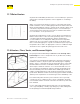
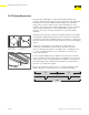
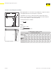
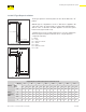
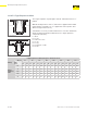
Table Of Contents
- About this Document
- Disclaimers
- Product Information
- Viega Manifolds
- Viega PureFlow Tubing
- Viega PureFlow Fittings
- Viega PureFlow System Design Considerations
- Water Service Installation
- Installing the ManaBloc
- Mounting the ManaBloc
- Installing Manifold Distribution Lines
- Installing the Viega PureFlow PEX Tubing System
- Fastening the Viega PureFlow System
- Installing Viega PureFlow Fittings
- Pressure Testing Viega PureFlow Systems
- System Disinfection
- Installer Checklist
- Limited Warranty

Fastening the Viega PureFlow System
69 of 88
IM-PF 724596 1021 PureFlow Water System (EN)
12.10.4 Z-Type Expansion Oset
The Z-type expansion oset integrates two 90° elbows that form a “Z”
pattern.
With this type of conguration ½ of the “L” dimension is applied to the
center area of the “Z” (represented as L1 in the table and illustration)
while ¼ of the “L” dimension would be applied to each of the top and
bottom areas (represented as L2).
Calculate the necessary L1 and L2 dimensions or use the chart below,
which was gured using the maximum run for a single expansion
compensator (50 feet).
L = 20.7"
L1 = ½ (L)
L1 = 20.7"/2 = 10.35"
L1 = 10.35"
L2 = ¼ (L)
L2 = 20.7"/4 = 5.18"
L2 = 5.18"
L2
L2
LT
L1
∆L
∆L
Anchor point
Z-Type Oset
Anchor point
L1 = 10.35"
L2 = 5.18"
L2 = 5.18"
Z-Type Expansion Example
Z-Type Expansion Oset (inch) per 50 linear feet of run
Tubing
ΔT(° F)
Tube
nom.
60 80 100 120 140 160 180 200
L1 L2 L1 L2 L1 L2 L1 L2 L1 L2 L1 L2 L1 L2 L1 L2
Viega
PureFlow
PEX
¾" 10.2 5.1 11.8 5.9 13.2 6.6 14.4 7.2 15.6 7.8 16.7 8.3 17.7 8.8 18.6 9.3
1" 11.6 5.8 13.4 6.7 15.0 7.5 16.4 8.2 17.7 8.8 18.9 9.5 20.1 10.0 21.1 10.6
1¼" 12.8 6.4 14.8 7.4 16.5 8.3 18.1 9.1 19.6 9.8 20.9 10.5 22.2 11.1 23.4 11.7
1½" 13.9 7.0 16.1 8.0 18.0 9.0 19.7 9.8 21.3 10.6 22.7 11.4 24.1 12.1 25.4 12.7
2" 15.9 8.0 18.4 9.2 20.5 10.3 22.5 11.3 24.3 12.2 26.0 13.0 27.6 13.8 29.1 14.5