
Install Instructions

Viega IM-PFMB 1007
15
5.1 MOUNTING THE MANABLOC
5.1 Mounting The
MANABLOC Between
Studs
NOTICE! Please leave this installation
guide for the homeowners reference.
Local code may also require
additional labeling directly adjacent to
the MANABLOC or on the inside of
any cover panel.
Dimensions in these instructions are
for 16" stud centers, and must be
adjusted for other stud spacing.
Once the general location of the
MANABLOC has been determined
(see page 11 for guidelines), the
MANABLOC may be mounted to a
suitable surface between a pair of
adjacent studs. For 16" stud spacing,
the MBB2 Mounting Straps can
simplify installation.
Tools Required
• Electric Drill
• Pencil or Pen
• Framing Square
• Tape Measure
• 3/4" and 1-1/4" Wood Drill Bits
• #2 Phillips Head Screwdriver
• Permanent Marking Pen*
• Tubing Cutter - Stock Code 21304
or HAK67
• PEX Press/Crimp Tool(s)*
• MANABLOC Wrench - Part No. MW1
(Compression Blocs only)
Additional Materials
• Wood or Drywall Screws - 1/2" or longer
• 1/2" or 3/4" Plywood - only required
when not mounting between studs
• Nylon Ties - Part No. HB14120
• PEX Distribution Line Tubing
• 3/4" or 1" Supply Line Tubing
• MANABLOC 1" Swivel Supply Fittings
• Fixture Transition Fittings
• Tubing Clamps and Hangers
• MANAPANEL Access Panel*
• Tubing Uncoiler*
• Tube Turnouts (recommended)
* Optional or may not be required for
some installations
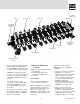
1. Lay the MANABLOC, plastic
brackets down, on a suitable flat
surface that is large enough to
accommodate the full-length of the
MANABLOC. Place a MBB2
Mounting Strap under each plastic
mounting bracket (located at the
top and bottom ends of the
MANABLOC). Attach the plastic
mounting bracket at one end of the
MANABLOC to the center two holes
of a Mounting Strap using the
provided self-tapping pan-head
screws. The screw heads must be
on the accessible side of the
mounting strap. Repeat at the other
end of the MANABLOC. Tighten
screws securely.
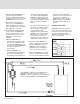
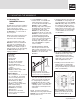
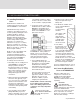
2. Standing behind the studwall,
measure up from the floor and
make a mark on the back of one of
the studs to represent the top of the
MANABLOC as shown in the
illustration.
This mark should be between 4 feet
and 6 feet from the floor but may
be at any height, provided the
height will allow all valves on the
MANABLOC to be accessible. With
a framing square or level, transfer
and mark the noted height on the
other stud.
NOTE: A residence intended for
disabled persons may require that the
MANABLOC be mounted lower in the
wall to provide access.
4' to 6'
from floor
Measure up from the floor while
standing behind the studwall. Mark a
location for the top of the MANABLOC.
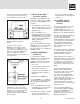
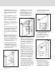
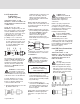
3. Standing behind the stud wall, hold
the MANABLOC facing away from
you and align the top of the UPPER
MBB2 Mounting Strap to the line on
the stud that you made in Step 2.
Loosely attach this Mounting Strap
flush to the back outer edge of one
stud using a 3/4" or longer drywall
or other suitable wood screw (A).
See illustration.
4. Line up the LOWER Mounting Strap
with the back outer edge of the
stud and attach it in the same
manner (B). Attach the remaining
strap ends (C & D) to the other
stud, and tighten all screws.
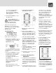
5. Standing in front of the wall, use a
framing square or straight edge
and mark the center line position of
the top and bottom ports onto both
studs (see illustration).
Mark the centers of the top and
bottom MANABLOC ports (A, B)
and the ports directly above and
below any divider plate (C, D)