
Install Instructions


Viega IM-MTL 0612
724607
48
movement of the tubing. However, all
systems must be installed per local
code requirements.
Tubing should be supported with
pipe hooks, metal pipe straps, bands,
brackets, or hangers suitable for the
size of tubing. Tubing supports should
be located at intervals to prevent or
damp out excessive vibration. When
connecting to equipment, tubing should
be anchored to prevent undue strains
on connection. Tubing cannot be
supported by other tubing.
Hangers and supports must conform
to the requirements of ANSI/MSSP 58,
pipe hangers and supports, materials,
design and manufacture. Supports,
hangers and anchors are to be installed
in a manner that does not interfere with
the free expansion and contraction
≥ 4"
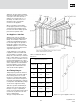
Figure 16.2: Spacing for sliding tube
hanger
of the tubing. All parts of the support
equipment need to be designed
and installed, not to disengage by
movement of the supported tubing.
Sliding hangers must be positioned so
that they cannot unintentionally become
rigid hangers when the system is in
use. Fig. 16.3 shows a sliding tubing
hanger that becomes a rigid hanger with
spacing in excess of 10".
16.5 Cutting Tubing
Copper tubing can be cut to length with
a tubing cutter or a fine-toothed metal
saw. It is not acceptable to cut the
tubing with an abrasive cutting wheel
or torch. The tubing ends must be
deburred both on the inside and outside
prior to insertion into the press fitting.
16.6 Threaded Adapter
Copper tubing can be cut to length with
a tubing cutter or a fine-toothed metal
saw. It is not acceptable to cut the
tubing with an abrasive cutting wheel
or torch. The tubing ends must be
deburred both on the inside and outside
prior to insertion into the press fitting.
The threaded end should be attached
before the press end.
Nominal Tube
Size (Inches)
Copper Tube
Max.
Span (Feet)
Min. Rod
Diameter
(Inches)
Up to 3/4 5 3/8
1 6 3/8
1-1/4 7 3/8
1-1/2 8 3/8
2 8 3/8
Table 16.6: Hanger Spacing
16.7 Pressure Testing
The pressure testing of installed
tubing is to be completed in
accordance with local codes or in the
absence of local codes in accordance
with NFPA 54 or NFPA 58 respectively.
16.8 Tubing Exposed to
Freezing Temperatures
In fuel gas systems, ProPressG can
be installed in ambient temperatures
down to -40° F.
16.9 Concealed Spaces
ProPressG has been examined to the
constructional and performance
criteria in the CSA requirement LC-4
and was found acceptable. Specific
performance tests were conducted to
evaluate the fittings for use in concealed
locations. See pages 36 through 42.
16.10 Underground
Installations
ProPressG and copper tubing is
approved for underground installations.
However, any installations must meet all
state and local codes, including those
for underground.
Proper authorization must be obtained
prior to underground installation.
16.11 Identification
Copper tubing for gas service must be
continuously marked in order to ensure
that it is not mistaken for any other
type of service. This is a very important
safety measure that must always be
completed before introducing gas into
the system. This marking, however,
is not required for the tubing in the
room in which gas-fired appliances
are located. Copper tubing is available
from some manufacturers with a yellow
covering indicating that the tubing is
gas tubing. Labels are also readily
available and can be added to the
tubing indicating that the system is a
fuel gas piping system. See Table 16.7
pipe marking guide.
Figure 16.3: Spacing for sliding
tube hanger
Figure 16.4: Threaded Adapter