
Install Instructions


Viega IM-MTL 0612
724607
47
diagonal to the joists may be installed
through holes drilled through the center
of the joists. These holes must be a
minimum of 1-1/2 times the O.D. of
the tubing. See Table 16.5 for more
information. This is to permit the
movement of the appliance.
When connecting a copper tubing
fuel gas piping system to a steel pipe,
cast bronze ProPressG fittings must
be used. These bronze fittings provide
protection from galvanic action.
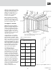
16.3 Appliance Stub Out
Appliance stub outs are created by
the installer using standard ProPressG
fittings. The assembly is attached to
a stud using standard tubing hangers
for structural support. This provides a
fixed point to attach a shut-off valve
and flexible appliance connector. Stub
out between floor and ceiling must be
supported and protected.
Copper tubing may connect directly
to appliances that do not vibrate and
are not portable. For example, copper
tubing can connect directly to a furnace,
boiler, or water heater. For connections
to dryers or stoves, a flexible connector
must be installed between the copper
tubing and the appliance. A gas shut-off
valve is required to be located within 6
feet of the appliance served. A union
fitting must be installed between the
shut-off valve and the appliance.
16.4 Tubing Hangers
Tubing hangers perform two functions.
The first function is to provide support
for the tubing system. The second
function is to guide the tubing during
expansion and contraction changes in
the length of the tubing due to changes
in temperature. Standard tubing clamps
can be used to support the tubing.
Table 16.6 specifies standard hanger
spacing. There are two main types of
hangers. One type is a rigid hanger
used to secure the tubing and not allow
movement in any direction. The other
type is a sliding hanger.
This type of hanger allows axial
Minimum Hole Dimensions
Tubing Size OD Hole Size
1/2" 5/8" 1"
3/4" 7/8" 1-3/8"
1" 1-1/8" 1-3/4"
1-1/4" 1-1/2" 2-1/4"
1-1/2" 1-5/8" 2-1/2"
2" 2-1/8" 3-1/4"
Table 16.5 Minimum drill hole
dimensions
Figure 16.1: Typical appliance stub out