
Install Instructions


Viega IM-MTL 0612
724607
52
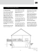
brace or bracket and run copper tube
through to the outside allowing
service personnel to be aware that it
is a semi-rigid system and damage
can be avoided.
The connection between the steel
system and copper system does not
create a corrosion concern if the
connection is made in a dry location
or a location that does not allow
moisture to collect at the connection.
The absence of continuous moisture
prevents the occurrence of galvanic
action and subsequent corrosion of
the steel pipe.
There are two basic types of fuel gas
piping layouts for residential
applications. One method includes a
gas main run through the building
with branch pipes running from the
main to supply gas to the various
appliances. The other is a home run
system with individual runs to each
appliance from a gas distribution
manifold installed between the meter
and the appliances. Depending on the
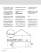
Figure 17.2: Typical manifold and individual runs
building being supplied, a combination
of these two systems may also be used.
A low pressure house layout with
branch piping is shown in figure 17.1.
A low pressure house layout with
individual runs is shown in
Figure 17.2.
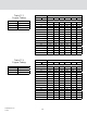
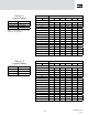
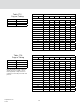
17.2 System Sizing
Fuel gas piping system using copper
tubing with ProPressG fittings may
be sized using Tables 17.1 through
17.9. The tables are intended to be
used when sizing in accordance with
the longest length method. The first step
in sizing is to determine the
appropriate table to use when sizing
the fuel gas piping system. Tables 17.1
through 17.7 are sizing tables for
natural gas. Tables 17.8 and 17.9 are
sizing tables for liquid propane gas.
The headings in the table indicate the
inlet gas pressure, the pressure drop
and the specific gravity. The gas
provider or utility will identify what
gas pressure and pressure drop to
use for sizing a fuel gas piping
system utilizing their fuel gas.
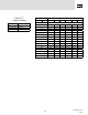
Once the proper table is selected,
the longest length method of sizing is
determined by measuring the distance
from the point of delivery (gas meter
or second stage regulator) to the most
remote appliance connection.
This distance will establish the length of
the piping system when determining the
pipe size.
Reading the values across the row for
the length of the piping system
indicate the cubic feet per hour of gas
that will flow for a given pipe size.
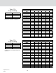
The copper tubing is sized based on
the total load of the system for each
section of the fuel gas piping system.
When a branch piping system is
installed, the longest length method
of sizing allows the branches to be
sized independently of the main runs
of piping.