
User Guide

Viega... The global leader in plumbing and heating systems.
301 N. Main, 9th Floor • Wichita, KS 67202 • Ph: 877-843-4262 • Fax: 800-976-9817 • E-Mail: service@viega.com • www.viega.com
PI-PR-18050-0309 (Digital Thermostat)
Product Instructions
Digital Thermostat
2 of 4
Mounting
Thermostats are typically mounted 48" to 60" from
the sub oor. Thermostats should not be located
in direct sunlight or in areas where solar gain
can occur. Other potential heat emitters are large
electrical gang boxes and dimmer switches. These
give off heat inside the wall and can cause a false
reading. Thermostats should always be located on
an interior wall.
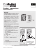
Remove white oval screw cover, located in the
middle of the thermostat. Then remove the #1
phillips screw. Pull the front cover off the black
back plate.
Thermostats have slotted mounting holes
simplifying leveling of the thermostat. Thermostats
should be installed with sleeves and anchors when
mounting into drywall.
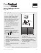
Connect the "R" terminal of the thermostat 1.
to the "R" terminal of the Zone Control. "R"
supplies power to the thermostat.
Connect the "W" terminal of the thermostat to 2.
the "W" terminal of the Zone Control. "W" is
the switching signal.
Connect the "C" terminal of the thermostat to 3.
the "C" terminal of the Zone Control. "C" is
common.
(See diagram to right)
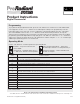
Wiring Thermostat to Powerhead
Connect a "C" and "R" terminals of the 1.
thermostat to transformer.
Connect the other "C" terminal and 2.
"W" terminal of the thermostat to Viega
Powerhead.
Up to 4 powerheads per thermostat may be 3.
connected.
(See diagram to right)
Digital Thermostat with
Transformer and up to 4
Powerheads
Digital Thermostat
Connected to a 4 or
6 Zone Control Box
C C R W
R W C
C C R W
24 VAC
TRANSFORMER
120 VAC
INPUT
WHITE
BLACK
Typical Wiring of Digital Thermostats
Wiring Thermostat to Zone Control