
Install Instructions

VIEGA • One Company... One Partner... Delivering System Solutions.
301 N. Main, Floor 9 • Wichita, KS 67202 • Ph: 877-Viega-NA • Fax: 316-425-7618 • E-Mail: service@viega.com • www.viega.com
PI-18033-1107
Product Instructions
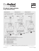
Pump and Boiler Relay
Wiring Diagram #1
Connecting the Pump and Boiler
Relay to a Viega Zone Control
Wiring Diagram #2
Connecting the Pump and Boiler
Relay to a Viega Thermostat
Wiring Diagram #3
Connecting the Pump and Boiler
Relay to a 2-wire thermostat
Terminal Identication:
T & T
Zone Control or thermostat connection
COM Common side of 24V transformer, for 3-wire thermostats
N Neutral wire of power input (120 V)
H Hot wire of power input (120 V)
3 Common terminal for 4 n/o and 4 n/c
4 n/o Normally open terminal
4 n/c Normally closed terminal
6 n/o Normally open terminal
6 n/c Normally closed terminal
5 Common terminal for 6 n/o and 6 n/c
Plant ID No. 9300-1076
2 of 2