
Install Instructions

VIEGA • One Company... One Partner... Delivering System Solutions.
301 N. Main, Floor 9 • Wichita, KS 67202 • Ph: 877-Viega-NA • Fax: 316-425-7618 • E-Mail: service@viega.com • www.viega.com
PI-18033-1107
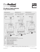
Product Instructions
Pump and Boiler Relay
Applications
The Viega LLC Pump and
Boiler Relay provides power to
circulators and can enable a boiler
as well. Control may be provided
from a Viega Zone Control or
Thermostat.
Features
External Indicator Lights
Universal Replaceability
Snap-in PC Board
Simple Wiring
Fully Enclosed Snap-out Relays
100% Factory Tested
Contractor Friendly PC Board
Layout
Universal Zone Control and
Thermostat Compatibility
UL Approved
Made in USA
Specications
Transformer Voltage:
120 VAC input
Maximum Load: 7.2 amps
Installation
Wiring connections must be made
in accordance with all applicable
electrical codes. Use copper
wire only. Failure to follow this
instruction can result in personal
injury or death and/or property
damage. 10-18 gauge wire
recommended for all 120 VAC
connections with 9 in. lbs. max
torque, 12-22 gauge wire for
thermostat connections with 9 in.
lbs. max torque.
Jumper placement:
The jumper is factory installed
between terminals H and 3 to
switch power on terminals
4 n/o and 4 n/c.
Operation
There are three common ways
to connect the Pump and Boiler
Relay:
With Zone Control:
Connect pump relay contacts of
Zone Control to “T T” terminals
on the relay. When the Zone
Control calls for heat, the relay is
energized and power is provided
to the circulator (and/or dry
contact to the boiler).
See wiring diagram #1 on reverse.
With Viega Thermostat:
Connect a 3-wire thermostat
(such as a Viega thermostat) to
the R, W, and COM terminals on
the relay. From the thermostat,
connect L to R, the arrow to W,
and N to 24 VAC/COM. When
the thermostat calls for heat, the
relay is energized and power is
provided to the circulator.
See wiring diagram #2 on reverse.
With 2-Wire Thermostat:
Connect a 2-wire thermostat to
the “T T” terminals on the relay.
When the thermostat calls for
heat, the relay is energized and
power is provided to the circulator
(and/or dry contact to the boiler).
See wiring diagram #3 on reverse.
Dimensions
Width 4-1/4”
Height 5-1/4”
Depth 2-3/4”
Troubleshooting
The external indicator lights show
full functionality of the Pump and
Boiler Relay. The green light
should always be on, indicating
that power is connected. If the
green light is out check the power
connections at terminals N and H.
The red light shows a call for heat,
indicating that power is being
supplied to the circulator (and/or a
boiler enable signal is provided).
If the Zone Control or thermostat
is calling for heat but the red
light is out, check the thermostat
wiring. If the red light is on but the
circulator is not running, check the
circulator connection to the relay.
Plant ID No. 9300-1076
1 of 2