
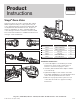
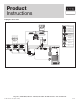
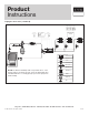
Product Overview

9 of 10
Product
Instructions
PI-PR 566490 0514 (Zone Valve)
Viega LLC, 301 N. Main, 9th Floor • Wichita, KS 67202 • Ph: 800-976-9819 • Fax: 316-425-7618
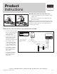
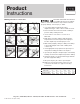
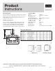
Tailpiece soldering
1. Cut the copper tubing cleanly with a tubing cutter.
2. Ream and de-burr the cut tubing.
3. Clean the inside of the tailpiece solder cup and the
outside of the copper tubing with a fitting brush and
emery cloth.
4. Brush an even layer of flux over the copper tubing
and within the tailpiece solder cup.
5. Insert the tubing into the solder cup until the copper
tubing seats fully, wipe off excess flux.
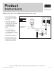
6. Heat the joint with a torch, moving the flame back
and forth on the tailpiece to heat evenly. Hold the
solder against the joint on the opposite side of the
flame until it melts. Run the solder 360° around
the tubing, the joint should appear full all the way
around. Avoid over-feeding the joint with solder.
The amount of solder required is equivalent to the
diameter of copper tubing being soldered.
7. Allow the soldered connections to cool before
connecting to the zone valve body.
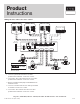
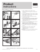
Testing
Leak Testing with Smart Connect®
Unpressed connections are located by pressurizing the
system with air or water. When testing with water the proper
pressure range is 15 psi to 85 psi maximum. Leak testing
with air can be dangerous at high pressures. When testing
with compressed air the proper pressure range is ½ psi to 45
psi maximum. Following a successful leak test, the system
may be pressure tested as specified in the next section.
Testing the system
The heating or cooling system that the zone valve is installed
into must be tested before it is commissioned. Air or water
may be used as the test medium. The following procedure is
recommended by Viega. Check the local building codes for
compliance or additional test requirements.
• Donotusewaterasatestmediuminsituationswhereit
may freeze.
• Checkthatallconnectionsaretightandproperlysealed.
• Makesureallvalvesareintheopenpositiontotestthe
integrity of the entire system.
• Connectmanifoldpressurizationkit(part#21210)tothe
manifold(s).
• Pressurizethesystemtonotlessthan100psior1.5
times the working pressure.
• Afterinitialpressurization,ensurepressurehasnot
dropped after 20 minutes. Fluctuations may occur due
to temperature fluctuations and tubing expansion. If a
drop has occurred add pressure to the system.
• Carryouttestforaminimumofonehour.
•
For leak detection, original Palmolive dishwashing soap
may be used. (Use ratio of two oz. soap to one gal. water).
•
If this is a radiant or snowmelt system pressure must be
maintained during the pour and floor covering installation.
• Oncesystemisdeemedleak-freetheconcretepour
and/or flooring finishes may be applied.