
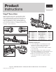
Product Overview

4 of 10
Product
Instructions
PI-PR 566490 0514 (Zone Valve)
Viega LLC, 301 N. Main, 9th Floor • Wichita, KS 67202 • Ph: 800-976-9819 • Fax: 316-425-7618
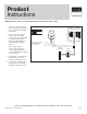
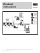
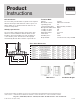
Zone Controls
1. Connect a yellow wire from the zone valve
powerhead to terminal 1 on the zone control.
2. Connect the other yellow wire from the zone valve
powerhead to terminal 2 on the zone control.
3. Remove and discard the jumper installed between
terminal 3 and 4.
4. Connect a red wire from the zone valve powerhead
to terminal 3 on the zone control.
5. Connect the other red wire from the zone valve
powerhead to terminal 4 on the zone control.
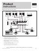
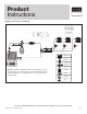
ZONE CONTROL (18060, 18062)
WITH OPTIONAL PRIORITY
OFF
ON
ZONE 4 PRIORITY
ZONE 1
ZONE 2 ZONE 3
ZONE 4
ZONE 4 RELAY
N/O N/CCOM
PUMP
END
SWITCH
ISOLATED
END
SWITCH
ZONE 1
ZONE 2
ZONE 3 ZONE 4
FUSE
(5 AMP MAX)
POWER IN
W C
R W CR
W CR WCR
1234
120 V AC
Power Supply
L
N
R
C
CC RW NTC A/B
Thermostat -18050
1 2 34 1234
C
O
B
W
RH
RC
G
Y
Thermostat -15116
C
O
B
W
RH
RC
G
Y
Thermostat -15117
C
O
B
W/E
RH
G
Y
Thermostat -15118
W2
Y2
RC
Viega
Yellow
Yellow
Red
Red
Viega
Yellow
Yellow
Red
Red
Viega
Yellow
Yellow
Red
Red
Viega
Yellow
Yellow
Red
Red
Line Voltage
Low Voltage
LEGEND: Zone Controls
Wiring the zone valve to the zone control