
User Guide

Indoor Sensor for Heating Controls
Product Instructions
Viega... The global leader in plumbing and heating systems.
301 N Main, 9th Floor, Wichita, KS 67202 • Ph: 877-843-4262 • Fax: 800-976-9817 • E-Mail: tech@viega.com • www.viega.com
PI-16016-02/04 2 of 2
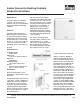
and pushed against the mounting
base until it rmly snaps into
place.
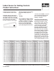
Testing
A good quality test meter capable
of measuring up to 5,000 kΩ (1kΩ
= 1000Ω) is required to measure
the sensor resistance. In addition
to this, the actual temperature
must be measured with either a
good quality digital thermometer,
or if one is not available, a second
sensor may be placed alongside
the one to be tested and the
readings compared.
First measure the temperature
using the thermometer and then
measure the resistance of the
sensor at the control. The wires
from the sensor must not be
connected to the control while
the test is being performed.
Using the chart below, estimate
the temperature measured by
the sensor. The sensor and the
thermometer readings should be
close. If the test meter reads a
very high resistance, there may
be a broken wire, a poor wiring
connection, or a defective sensor.
If the resistance is very low, the
wiring may be shorted, there may
be moisture in the sensor, or the
sensor may be defective. To test
testing instructions below and
connect the wires to the control.
The Indoor Sensor front cover is
installed by aligning the hinges on
the bottom of the front cover with
the bottom of the sensor mounting
base. The front cover is then
pivoted around the bottom hinge