
User Guide

Indoor Sensor for Heating Controls
Product Instructions
Viega... The global leader in plumbing and heating systems.
301 N Main, 9th Floor, Wichita, KS 67202 • Ph: 877-843-4262 • Fax: 800-976-9817 • E-Mail: tech@viega.com • www.viega.com
PI-16016-02/04 1 of 2
The Indoor Sensor should be
installed on an interior wall of the
desired zone to be controlled. Do
not mount the sensor in a location
that may be affected by localized
heat sources or cold drafts. It
may be necessary to install a
draft barrier and/or insulation
behind the enclosure in order to
prevent air from blowing through
the wiring hole and affecting the
sensor reading.
For surface mounting, attach
the Indoor Sensor directly to the
wall using two #6 - 1” screws.
The screws are inserted through
the mounting holes and must
be securely fastened to the wall.
If possible, at least one of the
screws should enter a wall stud.
Run two conductor 18 AWG or
similar wire between the Indoor
Sensor and the terminals on the
Heating Control. Insert the wires
through the hole provided in the
back of the sensor enclosure
and connect them to the indoor
sensor terminal block. Do not run
the wires parallel to telephone or
power lines. If the indoor sensor
wires are located in an area with
strong sources of electromagnetic
noise, shielded cable or twisted
pair should be used or the wires
can be run in a grounded metal
conduit. If using shielded cable,
one end of the shield wire should
be connected to the Com-Sen
terminals on the control and the
other end should remain free. The
shield must not be connected to
earth ground. Follow the sensor
Applications
The Indoor Sensor for Heating
Controls is an optional room
feedback sensor for both the Basic
Heating and Advanced Heating
Controls.
Features
The Indoor Sensor includes a
10kΩ thermistor which provides
accurate measurement of indoor
temperature. The sensor can be
mounted directly on a wall using
two #6 - 1” screws. The small size
of the sensor makes it visually
appealing and less noticeable on
the wall.
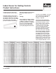
Speci cations
Packaged weight:
0.16lb. (72g)
Dimensions:
2-7/8” H x 2-7/8” W x 13/16” D
Approvals:
CSA NRTL/C
Operating Range:
-60 to 140°F (-50 to 60°C)
Sensor:
NTC thermistor, 10kΩ @ 77°F
(25°C +/- 0.2°C), β=3892
Installation
Note: The temperature sensor
(thermistor) is built into the sensor
enclosure.
To remove the Indoor Sensor front
cover, place a small screwdriver or
similar object into the small hole
located in the top of the sensor
enclosure. Push the screwdriver
against the plastic ap and pull
the top of the front cover so that it
pivots around the bottom edge of
the mounting base.