
Submittal Sheet

Viega... The global leader in plumbing, heating and pipe joining systems
301 N. Main, 9th Floor • Wichita, KS 67202 • Ph: 800-976-9819 • Fax: 316-425-7618 • www.viega.com
©2012, FostaPEX
®
, GeoFusion
®
, MegaPress
®
,
ProPress
®
, Seapress
®
and Viega
®
are registered trademarks of Viega GmbH & Co. Climate Mat
®
, Climate Panel
®
, Climate Trak
®
, ManaBloc
®
, PureFlow
®
, Radiant Wizard
®
,
S-no-Ice
®
, Smart Connect
®
, Snap Panel
®
, XL
®
and XL-C
®
are registered trademarks of Viega LLC. MiniBloc
™
, PolyAlloy
™
, ProRadiant
™
, Rapid Grid
™
, SmartLoop
™
and Zero Lead
™
are trademarks of Viega LLC;
ProPressG
™
and ViegaPEX
™
are trademarks of Viega GmbH & Co. KG.
TD-PR 0812 (Basic Heating Control)
TechData
Temperature Resistance Temperature Resistance
°F °C Ω °F °C Ω
-50 -46 490,813 90 32 7,334
-45 -43 405,710 95 35 6,532
-40 -40 336,606 100 38 5,828
-35 -37 280,279 105 41 5,210
-30 -34 234,196 110 43 4,665
-25 -32 196,358 115 46 4,184
-20 -29 165,180 120 49 3,760
-15 -26 139,402 125 52 3,383
-10 -23 118,018 130 54 3,050
-5 -21 100,221 135 57 2,754
0 -18 85,362 140 60 2,490
5 -15 72,918 145 63 2,255
10 -12 62,465 150 66 2,045
15 -9 53,658 155 68 1,857
20 -7 46,218 160 71 1,689
25 -4 39,913 165 74 1,538
30 -1 34,558 170 77 1,403
35 2 29,996 175 79 1,281
40 4 26,099 180 82 1,172
45 7 22,763 185 85 1,073
50 10 19,900 190 88 983
55 13 17,436 195 91 903
60 16 15,311 200 93 829
65 18 13,474 205 96 763
70 21 11,883 210 99 703
75 24 10,501 215 102 648
80 27 9,299 220 104 598
85 29 8,250 225 107 553
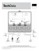
Test Sequence
Each step in the test sequence lasts 10 seconds.
During the test routine, the test sequence may
be paused by pressing the Test button. If the
Test button is not pressed again for 5 minutes while
the test sequence is paused, the control exits the
entire test routine. If the test sequence is paused,
the Test button can be pressed again to advance
to the next step. This can also be used to rapidly
advance through the test sequence. To reach the
desired step, repeatedly press and release the Test
button until the appropriate device and segment in
the display turn on.
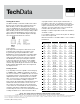
Testing Sensors
A good quality test meter capable of measuring up
to 5,000kΩ (1kΩ = 1000Ω ) is required to measure
the sensor resistance. In addition to this, the actual
temperature must be measured with a good quality
digital thermometer. If a thermometer is not avail-
able, a second sensor can be placed alongside the
one to be tested and the readings compared.
First measure the temperature using the thermometer
and then measure the resistance of the sensor at
the control. The wires from the sensor must not be
connected to the control while the test is performed.
Using the chart below, estimate the temperature
measured by the sensor. The sensor and thermometer
readings should be close. If the test meter reads a
Testing the Control
The Basic Heating Control has a built-in test routine
that is used to test the main control functions. The
Basic Heating Control continually monitors the
sensors and displays an error message whenever a
fault is found. See the following pages for a list of the
Basic Heating Control’s error messages and possible
causes. When the Test button is pressed, the test
light is turned on. The individual outputs and relays
are tested in the following test sequence.
very high resistance, there may be a broken wire, a
poor wiring connection, or a defective sensor. If the
resistance is very low, the wiring may be shorted, there
may be moisture in the sensor, or the sensor may be
defective. To test for a defective sensor, measure the
resistance directly at the sensor location.
Example: If outdoor temperature is 70° F the resistance
should be 11,883.
Do not apply voltage to a sensor at any time as damage
to the sensor may result.
Measured resistance should be within +/- 5% to what is
listed below.