Radiant Basic Heating Control Installation Manual March 2009
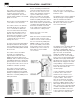
The Viega Basic Heating Control is designed to control the supply water temperature to a hydronic system in order to provide outdoor reset operation. The Basic Heating Control uses a floating action actuator mounted on a diverting or mixing valve to regulate the supply water temperature. The control has a Liquid Crystal Display (LCD) to view system status and operating information.
Contents 1 General Operation 1.1 Using the Control 1.2 Description of Display 4 4 2 Control Operation 2.1 General Operation 5 2.2 Control Features 5 3 Temperature Control 3.1 General Information 6 3.2 Installer Information 6 3.3 Advanced Information 6 4 Boiler Control 5 Installation 5.1 5.2 5.3 5.4 5.5 5.6 5.
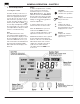
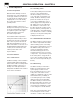
GENERAL OPERATION - CHAPTER 1 1 General Operation 1.1 Using the Control The Basic Heating Control uses a Liquid Crystal Display (LCD) as the method of supplying information. You use the LCD in order to set up and monitor the operation of your system. The Basic Heating Control has three push buttons (Item, , ) for selecting and adjusting settings. As you program your control, record your Adjust Menu settings for future reference or troubleshooting.
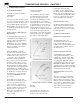
CONTROL OPERATION - CHAPTER 2 2 Control Operation 2.1 General Operation When the Basic Heating Control is powered up, the control displays the control type number in the LCD for 2 seconds. Next, the software version is displayed for 2 seconds. Finally, the control enters into the normal operating mode. The Basic Heating Control uses a floating action mixing or injection valve to vary the supply water temperature to a hydronic system. The supply water temperature is based on the outdoor temperature.
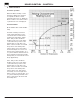
TEMPERATURE CONTROL - CHAPTER 3 3 Temperature Control 3.2 Installer Information 3.1 General Information Outdoor design (OUTDR DSGN) SYSTEM CIRCULATOR PUMP OPERATION (Sys Pmp) The system circulator pump contact (Sys Pmp, terminal 3) remains closed as long as the Basic Heating Control is not in Warm Weather Shut Down. During WWSD, the system Circulator is operated periodically based on the Exercise feature.
BOILER CONTROL - CHAPTER 4 4 Boiler Control 4.1 Boiler Operation When the Basic Heating Control determines that boiler operation is required, the Boiler contact terminals (5 and 6) close. While the Boiler contact is closed, the burner segment in the LCD is displayed. 4.2 Boiler Enable (Boiler Enable 30% / Boiler Enable 10%) The Basic Heating Control has a DIP switch that allows for the selection between a 30% boiler enable and a 10% boiler enable.
INSTALLATION - CHAPTER 5 5 Installation CAUTION Improper installation and operation of this control could result in damage to the equipment and possibly even personal injury. It is your responsibility to ensure that this control is safely installed according to all applicable codes and standards. This electronic control is not intended for use as a primary limit control. Other controls that are intended and certified as safety limits must be placed into the control circuit. 5.
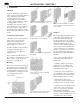
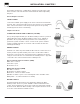
INSTALLATION - CHAPTER 5 Installing the Outdoor Sensor The Outdoor Sensor includes a 10kΩ thermistor that provides an accurate measurement of the outdoor temperature. The sensor is protected by a white U.V. resistant plastic enclosure. Remove the screw and pull the front cover off the sensor enclosure. The Outdoor Sensor can either be mounted directly onto a wall or a 2" x 4" electrical box. When the sensor is wall mounted, the wiring should enter through the back or bottom of the enclosure.
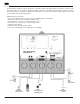
INSTALLATION - CHAPTER 5 5.2 Electrical Connections The installer should test to confirm that no voltage is present at any of the wires. Push the control into the base and slide it down until it snaps firmly into place. Powered Input Connection 120 Vac Power Connect the 120 VAC power supply to the Power L and Power N terminals (1 and 2). This connection provides power to the microprocessor and display of the control.
INSTALLATION - CHAPTER 5 Sensor and Unpowered Input Connections Do not apply power to these terminals as this will damage the control. Outdoor Sensor Connect the two wires from the Outdoor Sensor to the Com and Out terminals (11 and 12). The Outdoor Sensor is used by the Basic Heating Control to measure the outdoor air temperature. Supply Sensor Connect the two wires from the Supply Sensor to the Com and Mix terminals (10 and 11).
InstALLAtIon - CHAPtER 5 test the outputs SYSTEM CIRCULATOR PUMP (SYS PMP) If a system circulator pump is connected to the Sys Pmp terminal (3) and N terminal (4), make sure that power to the terminal block is off and install a jumper between the Power L and the Sys Pmp terminals (1 and 3). Install a second jumper between the Power N and N terminals (2 and 4). When power is applied to the Power L and Power N terminals (1 and 2), the system circulator pump should start.
INSTALLATION - CHAPTER 5 5.4 DIP Switch Settings The DIP switch settings on the control are very important and should be set to the appropriate settings prior to making any adjustments to the control through the User Interface. The DIP switch settings change the items that are available to be viewed and/or adjusted in the User Interface. Boiler Enable 30% Boiler Enable 10% The position of this switch determines at which valve position the control will close the Boiler contact under normal conditions.
INSTALLATION - CHAPTER 5 5.6 Adjust Menu Display Settings To make an adjustment to a setting in the control, press and hold simultaneously for 1 second, the Item, and buttons. The display will then show the word ADJUST in the top right corner. Then select the desired item using the Item button. Finally, use the and/or button to make the adjustment. See sections 3.2 and 3.3 (page 6) for further discussion on these items and their effect on control operation. ROOM The desired room temperature.
INSTALLATION - CHAPTER 5 5.7 Testing the Control Testing Sensors The Basic Heating Control has a built-in test routine that is used to test the main control functions. The Basic Heating Control continually monitors the sensors and displays an error message whenever a fault is found. See the following pages for a list of the Basic Heating Control’s error messages and possible causes. When the Test button is pressed, the test light is turned on.
TROUBLESHOOTING - CHAPTER 6 6 Troubleshooting When troubleshooting any heating system, it is always a good idea to establish a set routine to follow. By following a consistent routine, many hours of potential headaches can be avoided. Below is an example of a sequence that can be used when diagnosing or troubleshooting problems in a hydronic heating system. Establish the problem. Get as much information from the customer as possible about the problem.
TROUBLESHOOTING - CHAPTER 6 Error Messages E01 The control was unable to read a piece of information from its EEPROM. This error can be caused by a noisy power source. The control will load the factory defaults and stop operation until the settings are verified. Shr (OUTDR) The control is no longer able to read the Outdoor sensor due to a short circuit. In this case the control assumes an outdoor temperature of 32°F (0°C) and continues operation. Locate the problem as described in Section 5.7.
MECHANICAL AND ELECTRICAL DIAGRAMS - CHAPTER 7 Pump Pump Pump Pump VIEGA 1-800-976-9819 18 PI-16015-03/09
MECHANICAL AND ELECTRICAL DIAGRAMS - CHAPTER 7 * * Three Position Actuator: White wire common, green wire open, brown wire close.
TECHNICAL DATA - CHAPTER 8 Technical Data Control Packaged Weight Dimensions Approvals Ambient Conditions Power Supply Floating Output Relays Sensors Microprocessor PID control; this is not a safety (limit) control 3.1 lbs. (1420 g) Enclosure black PVC plastic 6-5/8" H x 7-9/16" W x 2-13/16" D (170 x 193 x 72 mm) CSA C US, meets ICES & FCC regulations for EMI/RFI Indoor use only, 32 to 102°F (0 to 39°C), <90% RH non-condensing 120 VAC +/- 10% 50/60 Hz 1300 VA 24 VAC 0.
NOTES VIEGA 1-800-976-9819 21 PI-16015-03/09
NOTES VIEGA 1-800-976-9819 22 PI-16015-03/09
NOTES VIEGA 1-800-976-9819 23 PI-16015-03/09
Basic Heating Control Installation and Operation Manual ProPress® System ProPress® System ProPressG™ System Flameless copper press technology. Flameless copper fire safety press technology. Flameless copper fuel gas press technology. PureFlow® System ProRadiant™ Systems S-no-Ice® System Flexible PEX tubing plumbing technology. Comfortable, efficient heating technology. The global leader in plumbing and heating systems.