
Install Instructions

3 of 3
Product
Instructions
PI-PR 520946 0915 (Powerhead for Stainless Manifold 24v 4 wire) (EN ES FR)
Viega LLC, 100 N. Broadway, 6
th
Floor • Wichita, KS 67202 • Ph: 800-976-9819 • Fax: 316-425-7618
This document subject to updates. For the most current Viega technical literature please visit www.viega.us.
Click Services -> Click Electronic Literature Downloads -> Select Product Line -> Select Desired Document
Para ver las instrucciones en español visite www.viega.us -> Services -> Electronic
Literature Downloads -> French and Spanish Documents -> Documento Deseado
Pour obtenir des instructions en français visite www.viega.us -> Services -> Electronic
Literature Downloads -> French and Spanish Documents -> Document Désiré
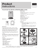
Wiring Schematic − Thermostat and Powerheads with Zone Control
NOTE: Installation by a licensed electrician is recommended. Installation and use of this equipment should be in
accordance with provisions of the U.S. national electric code, applicable local code and pertinent industry standards.
1. Factory jumper between 3 and 4 must be removed for
use with 4-wire powerhead.
2. Install powerheads on system return manifold.
3. Up to four powerheads may be connected to each zone.
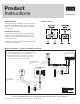
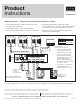
Part Numbers:
15116, 15117 and 15118
1. Connect the "RC" terminal
from the thermostat to "R"
terminal on the zone control
2. Connect the "W" terminal
from the thermostat to "W"
terminal on the zone control,
for part number 15118
connect "W/E" terminal from
the thermostat to "W" terminal
on the zone control
3. Connect the "C" terminal from
the thermostat to the "C"
terminal on the zone control
Line Voltage
Low Voltage
LEGEND: Thermostat
4. Part number 18060 may be used for up to eight
powerheads per zone control box. Part number 18062 may
be used for up to 16 powerheads per zone control box.
5. Refer to the zone control and thermostat product
instruction for further details.
Up to four powerheads may
be connected to each zone.
ZONE CONTROL (18060, 18062)
WITH OPTIONAL PRIORITY
OFF
ON
ZONE 4 PRIORITY
ZONE 1
ZONE 2
ZONE 3
ZONE 4
ZONE 4 RELAY
N/ON/CCOM
PUMP
END
SWITCH
ISOLATED
END
SWITCH
ZONE 1 ZONE 2 ZONE 3
ZONE 4
FUSE
(5 AMP MAX)
POWER IN
WC
R
W C
R
W C
R
WC
R
12
3 4
120 V AC
Power Supply
L
N
Yellow
Yellow
Red
Red
Yellow
Yellow
Red
Red
Yellow
Yellow
Red
Red
R
C
C C RW NTCA/B
Thermostat -18050
POWERHEAD (15070)
FOR USE WITH
STAINLESS MANIFOLD
2 WIRE, 24 V,
POWERHEAD (15069)
FOR USE WITH
STAINLESS MANIFOL
D
4 WIRE, 24 V,
JUMPER
3&4
JUMPER
3&4
IF PRIORITY
IS USED
1234 123 4 123 4
C
O
B
W
RH
RC
G
Y
Thermostat -15116
C
O
B
W
RH
RC
G
Y
Thermostat -15117
C
O
B
W/E
RH
G
Y
Thermostat -15118
W2
Y2
RC