
Install Instructions

2 of 3
Product
Instructions
PI-PR 520946 0915 (Powerhead for Stainless Manifold 24v 4 wire) (EN ES FR)
Viega LLC, 100 N. Broadway, 6
th
Floor • Wichita, KS 67202 • Ph: 800-976-9819 • Fax: 316-425-7618
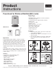
ON/OFF Indicator
The powerhead has a cylinder on the top that will raise
and expose blue when the valve is open. You will be
unable to see any blue when the valve is in its normal
closed position.
Initially-Open Function
The powerhead is delivered in the open position. This
allows for easier installations and also allows for the
installer to pressure and flow test each circuit before
connecting the power.
This function is disengaged automatically after the first
6 minutes of powered use.
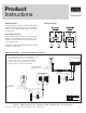
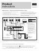
Wiring Schematic − Thermostat with Powerheads
End Switch State
1. Up to (4) powerheads may be controlled from a single
thermostat without the use of an external relay.
2. Powerhead provides a non-powered, end switch
contact closure only upon actuation (valve open).
3. For part number 15118 use “W/E” terminal.
Line Voltage
Low Voltage
LEGEND: Thermostat
Class II
Transformer
C
R
120 V AC
Power Supply
N
L
Red
Red
Yellow
Yellow
TO T-T BOILER CONTACT, PUMP
RELAY OR OTHER AUXILIAR
Y
DEVICE REQUIRING CONTAC
T
CLOSURE.
C
O
B
W
RH
RC
G
Y
Thermostat -15116,
15117, 15118
CC RW NTC A/B
Thermostat -18050
Class II
Transformer
C
R
120 V AC
Power Supply
N
L
Red
Red
Yellow
Yellow
TO T-T BOILER CONTACT, PUMP
RELAY OR OTHER AUXILIAR
Y
DEVICE REQUIRING CONTAC
T
CLOSURE.
.