GSM DOOR INTERCOM SYSTEM (Vandal Resistant) ` Example panel only TECHNICAL MANUAL EDITION 2.0.
PAGE 2 of 36 VR GSM DOOR INTERCOM TECHNICAL MANUAL VER2.0.
CONTENTS Manual introduction System introduction Precautionary advice System components Intercom module Expansion button modules VX800 Codelock Door panel mounting frames Power supply Wiring diagrams Accessories wiring guide Cable guide Installation overview Panel care Testing, power up and reset Programming Programming by text message Programming by dial in System operation User commands Checking the balance of a Pay As You Go SIM Understanding the signal strength test Dial in priority Call button record k
MANUAL INTRODUCTION The information in this manual is intended as an installation and commissioning guide for the Vandal resistant GSM door intercom systems using the Art.150 self contained GSM audio module. This manual should be read carefully before the installation commences. Any damage caused to the equipment due to faulty installations where the information in this manual has not been followed is not the responsibility of Videx Security Ltd.
PRECAUTIONARY ADVICE o When mounting the GSM antenna, choose a location which is away from human interaction and away from the intercom panel. Route the GSM antenna cable from the intercom panel so that it is separate from the power supply cables and microphone wire. o Always ensure the power is off to the intercom panel before inserting or removing the SIM card. o New SIM cards will need registering before they can be used. Full details of how this is done can normally be found in the SIM card pack.
SYSTEM COMPONENTS A system comprises of an intercom panel (which includes the Art.150 module), power supply, SIM card and antenna. The intercom panel can be customised to the installation requirements by including proximity access control, coded access or bioaccess and also including the correct number of call buttons. ART.150 MODULE The intercom panel can be a standard or custom size vandal resistant panel or could be made up as a modular vandal resistant panel using modules from the VR4K range.
CONNECTION +12V 0V NC NO C AI PE a b c d e C1 C2 AO DESCRIPTION 12Vdc input to power the module Ground connection Normally closed connection of dry contact relay Relay contacts: 3A@24Vdc Normally open connection of dry contact relay 3A@120Vac Common connection of dry contact relay Auxiliary input (Between AI & C1 triggers AO, Between AI & C2 sends an SMS to the number stored in memory location 020 Exit button input (Between PE & C1) Triggers relay for programmed time.
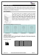
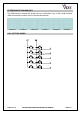
EXTENSION BUTTON MODULES The GSM intercom module will accept up to ten call buttons. Any of the vandal resistant 4000 series button modules can be used as shown below. VR4KBM-4 VR4KBM-5 VR4KBM-6 VR4KBM-7 VR4KBM-8 VR4KBM-9 CALL BUTTON WIRING PAGE 8 of 36 VR GSM DOOR INTERCOM TECHNICAL MANUAL VER2.0.
CODELOCK MODULE (VR4KCLM, 800CL) The codelock includes three relay outputs (Only 2 on the 800CL), two push to exit button inputs and operates from a 12-24V ac/dc power supply. Up to 2 unique codes can be programmed, each in the range of 4-8 digits. Relay time can be programmed from 01 – 99 seconds or set to latching mode with a relay time of 00 (To latch, type in the code followed by Enter, to unlatch, type in the code followed by clear).
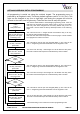
ART.4800 CODELOCK INITIAL PROGRAMMING All programming is carried out using the codelock keypad. The programming menu is protected by an engineer’s code. The factory default engineers code is 111111 (6x1). This code can be changed to any four to eight digit code during the program but must be different to the codes used to gain entry. Follow the flow chart to setup the system:Enter the engineers code. 111111 Then press enter The red LED will illuminate to acknowledge programming mode.
ART.4800 CODELOCK REPROGRAMMING GUIDE Engineers code Relay 1 code Relay 2 code Relay 3 code Enter the engineer’s code RED Light will illuminate * Press Enter Re-Enter the engineer’s code Alternatively enter a new engineer’s code (4-8 digits) Relay 1 Time Relay 2 Time Relay 3 Time Press Enter Enter relay code Relay code (4 – 8 digits) operates the door or gate.
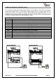
DOOR PANEL MOUNTING FRAMES (VR4K SERIES) Both surface and flush mounting frames are available. The size of the frame will depend on the number of modules that make up the door panel. The last digit of the frame code indicates the number of modules it will take. Frames are available in gun metal gray finish, chrome finish (Suffix \C to the frame code) or gold finish (Suffix \G to the frame code).
WIRING DIAGRAMS PAGE 13 of 36 VR GSM DOOR INTERCOM TECHNICAL MANUAL VER2.0.
PUSH TO EXIT BUTTON AND AUXILIARY INPUTS/OUTPUTS PUSH TO EXIT BUTTON, TRIGGERS RELAY FOR PROGRAMMED TIME AUXILIARY INPUT, TRIGGERS AUXILIARY OUTPUT (AO) AUXILIARY OUTPUT (OPEN COLLECTOR), TRIGGERS WHEN C1 & AI ARE SHORTED AUXILIARY INPUT, SENDS A SMS MESSAGE TO THE TELEPHONE NUMBER STORED IN MEMORY LOCATION 020 (NOTE: Once triggered, it can’t be triggered again for 4 minutes. This avoids multiple SMS messages being sent for the same alarm) PAGE 14 of 36 VR GSM DOOR INTERCOM TECHNICAL MANUAL VER2.0.
CABLE SIZE GUIDE Connections for power supply output to intercom panel and lock release connections. 20m 50m 100m 0.5mm² 1.0mm² 1.5mm² Connections The power supply should be located as close to the intercom panel as possible for best performance. Maximum acceptable resistance for above cables = 3Ω INSTALLATION - Check that all components are free from damage before installing (Do not proceed with installation in the event of damage). - Keep all packaging away from children.
TESTING, POWER UP AND RESET After connecting the power supply, antenna, lock output and auxiliary devices as shown in this manual and before powering up, a SIM card must be installed. The SIM holder can be found inside the Art.150 modul. A SIM card from any supplier can be used. Simply push the SIM holder in the direction of ‘OPEN’ and then lift. Insert the SIM card (It will only fit one way) and then push back down and into the ‘LOCK’ position.
PROGRAMMING Programming can be carried out either by text message or by dialling into the intercom panel (Certain programming features can only be setup by text message). IMPORTANT NOTE: When you are required to use “ in a text message it is very important to use the correct symbol and not for example ‘ (Or two ‘ single apostrophes side by side which you will see look the same but will be interoperated differently by the SMS intercom panel).
Most of the commands support the ? feature. When this is added to the end of the text message, a confirmation text message will be sent back to the sender indicating the new data has been received and stored. OPTIONAL ?: When sending text messages there may be a delay from when you send the message to when it is received by the intercom panel depending on how congested the network is.
STORING A TELEPHONE NUMBER FOR DIAL IN DOOR RELEASE Dial in door release allows users of telephones with their number stored to release the door/gate simply by dialling the telephone number of the SIM in the intercom panel. The intercom panel will check the callers ID when it receives a call and if it matches the list of stored numbers, it will clear the call down (Avoiding the caller being charged for the call) and will activate the relay for the programmed time.
1111SPTnn? Store the time nn x 20 seconds (e.g. nn = 02, time = 40 seconds. Also send a confirmation text back to the sender. 1111SPT? Query the current stored time. A text message will be sent to the sender showing the stored time. (Remember to multiple the number in the received text by 20 seconds) SET RELAY TIME The relay time can be from 01 – 99 seconds or latching (Set the relay time to 00 for latched mode. In latch mode, the relay will stay energised until the command is send again).
1111AOM? Query the current stored mode. A text message will be sent to the sender showing the stored mode. CHANGING THE FOUR DIGIT CODE The four digit code can be any combination of numbers 0-9 but must be 4 digits long. The code allows access to the programming menu in dial in mode and must be used when sending text messages to the intercom panel.
DIVERT SETUP Divert can be set for any or all of the call buttons. When set, if a call is not answered within the divert time, the call will be forwarded to the second number and the call time will be refreshed. The following table shows the value of nm used in the programming messages. Default is all diverts disabled (m=0).
Change message to HouseAlarm 1111SMS”HouseAlarm” Note: The message can be a maximum of 20 characters long and can not include spaces or “. The memory location used to store the telephone where the text will be send is also the same memory location used for the divert telephone number for button 10 (i.e. 020). PROGRAM BY ‘AT’ COMMANDS This is an advanced feature of the system which can allow an AT format command to be sent to the OEM GSM module.
PROGRAMMING BY DIAL IN Note: programming dial in cannot be used from telephones which are already programmed to open the door when they dial the intercom panel. When dialling into the GSM intercom from a telephone number which is already stored as one of the call button telephone numbers it will be necessary be press to switch from call mode to programming mode. To gain access to the programming menu via dial in, follows these steps:1. Call the telephone number of the intercom panel. 2.
STORING A CALL BUTTON TELEPHONE NUMBER Telephone numbers can be stored for the ten available call buttons. Each call button can call up to two telephone numbers (If the first is busy or not answered in a certain time it can call the second number if the divert facility is setup). The following programming sequence stores telephone numbers. nnyyyyyyyyyyy# Store the telephone number yyyyyyyyyyy in position nn nn# Delete the telephone number yyyyyyyyyyy in position nn nn can be found using the table.
SET DAYS TO WAIT BEFORE MAKING A CALL In the event the intercom panel is not used for long periods of time it could be possible that the network disconnects it. To prevent this from happening it is possible to program a time period (From 01 – 99 days) to wait before the intercom panel makes a short call to refresh the connection. This time period is reset after each call made on the system and will only happen if the full time period elapses without any incoming or outgoing calls.
SYSTEM OPERATION TO MAKE A CALL FROM THE INTERCOM PANEL Press the required call button. Two beeps will be heard to indicate the call has been placed and the red LED will illuminate. If a mistake is made, press any other button to clear the call (A long beep followed by a short beep will be heard to confirm the call has been cleared. (Note: If the same button is pressed after five seconds of placing the call this will also clear the call down. Pressing the same button before five seconds will do nothing).
CHECKING THE BALANCE *Note: The balance can only be checked if the correct balance check string has previously been stored using the SDL code explained earlier in the manual. The intercom also has the facility to monitor the available credit and then text you to inform you when it has fell below £5.00, €5.00 or $5.00. It will then remind you with another text after every 5 calls until the credit is either increased or it runs out.
RECORD SHEET INTERCOM PANEL TELEPHONE No. IMEI NUMBER MASTER CODE BUTTON Button 1 Button 1 (Divert) Button 2 Button 2 (Divert) Button 3 Button 3 (Divert) Button 4 Button 4 (Divert) Button 5 Button 5 (Divert) Button 6 Button 6 (Divert) Button 7 Button 7 (Divert) Button 8 Button 8 (Divert) Button 9 Button 9 (Divert) Button 10 Button 10 (Divert) MEM. LOCATION 001 011 002 012 003 013 004 014 005 015 006 016 007 017 008 018 009 019 010 020 USER NAME TELEPHONE No.
125 126 127 128 129 130 131 132 133 134 135 136 137 138 139 140 141 142 143 144 145 146 147 148 149 150 151 152 153 154 155 156 157 158 159 160 161 162 163 164 165 166 167 168 169 170 171 172 173 174 175 PAGE 30 of 36 201 202 203 204 205 206 207 208 209 210 211 212 213 214 215 216 217 218 219 220 221 222 223 224 225 226 227 228 229 230 231 232 233 234 235 236 237 238 239 240 241 242 243 244 245 246 247 248 249 250 VR GSM DOOR INTERCOM TECHNICAL MANUAL VER2.0.
UNDERSTANDING THE BEEPS Functions and errors are indicated by beeps from the intercom panel. The following will help you understand the different beeps heard and what, if anything needs to be done in response to the beeps. BEEP Short beeps at 1 second intervals Single short beep while the system is in standby and not being used. Two short beeps followed by a long beep Long beep followed by short beep while the system is in standby. REASON Relay or auxiliary output activated.
TROUBLE SHOOTING SYMPTOM Interference on the speech TEST The intercom panel repeatedly beeps twice and the name plate back light of the module (Not additional button modules) does not illuminate. Check the power supply is of adequate voltage as show earlier in this manual and that the jumper JP1 is in the correct position. Check the signal strength ‘1111SIG?’. If the signal strength is to low the GSM module which increase it’s power to compensate causing interference with the speech circuits.
Enfora certifies that the Enfora Enabler IIG TM MHz GSM Radio Module FCC ID: MIVMLG0208) complies with the RF hazard requirements applicable to broadband PCS equipment operating under the authority of 47 CFR Part 22 or Part 24, Subpart E of the FCC Rules and Regulations. This certificate is contingent upon installation, operation and use of the Enabler IIG module and its host product in accordance with all instructions provided to both EOM and end used.
Date 07/04/2009 10/12/2010 PAGE 34 of 36 Software Version GSMVR0.0.1 GSMVR1.0.0 Revision Initial release New hardware release. Additional reset software added. Busy LED added VR GSM DOOR INTERCOM TECHNICAL MANUAL VER2.0.
PAGE 35 of 36 VR GSM DOOR INTERCOM TECHNICAL MANUAL VER2.0.
Northern Office Videx Security Ltd Unit 4-7 Chillingham Ind. Est. Newcastle Upon Tyne NE6 2XX TEL 0870 300 1240 FAX 0191 224 5678 Southern Office 1 Osprey Trinity Park Trinity Way London E4 8TD FAX 0208 523 5825 TECHNICAL SUPPORT tech@videx-security.com TEL 0191 224 3174 FAX 0191 224 4938 http://www.videx-security.com PAGE 36 of 36 VR GSM DOOR INTERCOM TECHNICAL MANUAL VER2.0.