4000 SERIES (4+1) VANDAL RESISTANT DOOR ENTRY SYSTEM TECHNICAL MANUAL EDITION 1.
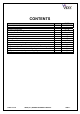
CONTENTS Manual introduction System introduction System components Codelock programming instructions Accessories Installation Cable size guide Testing the system Panel care Accessories connection guide Single entrance single button audio wiring diagram Single or multiple entrance, multiple button audio wiring diagram Single entrance video system wiring diagram Multiple entrance video system wiring diagram Troubleshooting guide PAGE 2 of 24 VR4K (4+1) SERIES TECHNICAL MANUAL PAGE 3 3 3 – 13 15 – 16 13 – 1
MANUAL INTRODUCTION The information in this manual is intended as an installation and commissioning guide for the vandal resistant 4000 Series door entry systems. This manual should be read carefully before the installation commences. Any damage caused to the equipment due to faulty installations where the information in this manual has not been followed is not the responsibility of Videx Security Ltd. VIDEX run free training courses for engineers who are not familiar with the Videx product range.
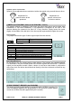
AMPLIFIER (Art.136) The amplifier is the most important part of the system and controls the operation of the system including speech, door release call to apartment etc. It contains a microprocessor which controls all of these features.
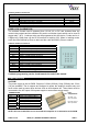
Amplifier speech volume POTS Speech volume adjustments are carried out at the door panel using a small trimmer driver. Adjustment for speech volume at the apartment Adjustment for speech volume level at the door station CAMERA (Art.VR4KCMM – Mono & Art.VR4KCMC - Colour) The camera module is available in both mono and colour and can be set for either coax installations or non-coax installations. A tilt adjustment is available on the rear of the camera allowing the camera to be tilted 10° in any direction.
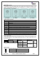
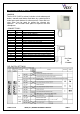
Proximity module connections Connection 12V RK LR LG Function 0V power connection 12Vdc power connection Serial data connection to controller Red LED control line (Also controls the internal sounder) Green LED control line (Also controls the internal sounder) Colour Grey White Yellow Brown Green CODE LOCK (Art.
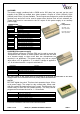
Art.520MR This power supply combines both a 520M and a 506 relay into one and can be used instead of the 520M on multiple door video systems. Outputs of 12Vdc (200mA), 8Vdc (300mA) and 13Vac (1A) are available. The dc outputs are designed to power the amplifier modules only and must not be used to power other devices such as lock releases etc. These items must be connected to the AC output of this power supply or an auxiliary power supply. CONNECTIONS Terminal +12 +8 ~ Function 12Vdc output (200mA Max.
TELEPHONE Art.3111 The Art.3111 is a white ABS plastic wall mounting electronic call telephone and includes a lock release push button and spare dry contact button. There is a three position call volume control external to the top left side of the telephone. Art.3011 Smart line phone includes a lock release push button only.
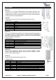
VIDEOPHONES & MONITORS Art.3312 The Art.3312 (3412 for colour) includes a lock release push button, camera recall button and three dry contact push to make spare push buttons for other services. Coax and noncoax video can be used by setting the relevant dipswitches. An Art.3980 back plate is required with this videophone.
Art.3313 The Art.3313 (3413 for colour) includes a lock release push button and two dry contact push to make spare push buttons for other services. An Art.3980 back plate is required with this videophone.
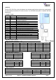
Art.5418 The 5418 colour Eclipse is available surface, flush and with a handset. Features include full duplex speech, door release, latching relay, 2x momentary outputs and timed privacy.
5418 VIDEO SETUP & PROGRAMMING 3 Way dip-switch 1 2 3 ON OFF ON OFF ON ON Switch 3 = Video end of line resistor Video Mode Coax video signal Balanced video signal To enter programming mode to carryout the following settings, press the two following buttons at the same time (left button of the volume control and the right button of the colour intensity control) (far left button and far right button together). When the programming mode is entered LED 1 (The LED next to the ●● button) starts flashing.
• • Press the “ ” button again to set the privacy duration. Each time the button is pressed, it will increase the privacy duration by 15 minutes (starting from 0 up to a maximum of 20 hours i.e. pressing the button 8 times = 2 hours up to a maximum of 80 presses for 20 hours). Once the required privacy duration has been reached, wait 3 seconds for the exit beep.
INSTALLATION The wiring diagram towards the back of this manual should be followed carefully. Heavy duty conductors on wiring diagrams are shown heavily outlined, these wires should be doubled up. - Check that all components are free from damage before installing (Do not proceed with installation in the event of damage). Keep all packaging away from children. Do not obstruct the ventilation openings or slots on any of the devices.
VR4KCLM CODELOCK INITIAL PROGRAMMING All programming is carried out using the codelock keypad. The programming menu is protected by an engineer’s code. The factory default engineers code is 111111 (6x1). This code can be changed to any four to eight digit code during the program but must be different to the codes used to gain entry. Follow the flow chart to setup the system:Enter the engineers code. 111111 Then press enter The red LED will illuminate to acknowledge programming mode.
VR4KCLM CODELOCK REPROGRAMMING GUIDE Engineers code Relay 1 code Relay 2 code Relay 3 code Enter the engineer’s code RED Light will illuminate * Press Enter Re-Enter the engineer’s code Alternatively enter a new engineer’s code (4-8 digits) Relay 1 Time Relay 2 Time Relay 3 Time Press Enter Enter relay code Relay code (4 – 8 digits) operates the door or gate.
CABLE SIZE GUIDE Suitable cables for this system are CW1308 and YY cable (Other similar cables are also suitable) Care should be taken to avoid excessive voltage drop. Follow the guide lines below. Connections from door panel to telephones/videophones. Connections 50m 100m 200m 0.35mm² 0. 5mm² 0.75mm² Power 0.25mm² 0.35mm² 0.5mm² All Others 300m 1.00mm² 0.75mm² 400m 1.5mm² 1.
Adding the 4800 codelock to a panel PAGE 18 of 24 VR4K (4+1) SERIES TECHNICAL MANUAL VER1.
WIRING DIAGRAMS The diagrams in this manual are examples. If you require a special diagram to show a particular installation, please e-mail your request to tech@videx-security.com along with your parts list and a description of your system. PAGE 19 of 24 VR4K (4+1) SERIES TECHNICAL MANUAL VER1.
PAGE 20 of 24 VR4K (4+1) SERIES TECHNICAL MANUAL VER1.
PAGE 21 of 24 VR4K (4+1) SERIES TECHNICAL MANUAL VER1.
PAGE 22 of 24 VR4K (4+1) SERIES TECHNICAL MANUAL VER1.
TROUBLE SHOOTING SYMPTOM TEST No speech from the door panel to the Check terminal 2 on the amplifier for continuity to terminal 2 on the telephone. telephone. Check the voltage drops to approx. 1Vdc after the handset is lifted. (If not try another telephone) If all else fails try another amplifier at the door station No speech from the telephone to the door Check terminal 1 on the door panel amplifier for continuity back to terminal 1 on the telephone. panel. Check the voltage drops to approx.
Northern Office Videx Security Ltd Unit 4-7 Chillingham Ind. Est. Newcastle Upon Tyne NE6 2XX TEL 0870 300 1240 FAX 0191 224 5678 Southern Office 1 Osprey Trinity Park Trinity Way London E4 8TD FAX 0208 523 5825 TECHNICAL SUPPORT tech@videx-security.com TEL 0191 224 3174 FAX 0191 224 4938 http://www.videx-security.com PAGE 24 of 24 VR4K (4+1) SERIES TECHNICAL MANUAL VER1.