
User manual


Small Vision System User Manual 39
4.1 Calibration Procedure
An automatic calibration procedure using five image pairs of a planar calibration target is included as
part of the smallv program. Given the image pairs of the calibration object, the system automatically
locates corner features in the target, fits a model of the target to the images, and finally produces an
estimate for the left and right camera intrinsics, the stereo head extrinsics, and the rectification matrices
0
P ,
1
P ,
0
H , and
1
H . These values are then used by smallv, and can also be saved as a parameter file
for later re-use. More information about the
calibration procedure can be found in the
Calibration Addendum to the User’s Manual.
4.1.1 Calibration procedure steps
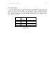
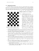
1. Create the calibration object. Print out a
copy of the file data/check.pdf
(Figure 4-1) and paste it to a surface that
is as flat as possible. We use a wooden
cutting board as a backing surface at SRI.
2. Start the smallv application and start
capturing video. It is recommended that
you set the video resolution to at least
320x120 in order to get enough detail of
the calibration object. A calibration
computed when capturing video at a
higher resolution can be used for future
video captured at any resolution with the
same cameras.
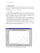
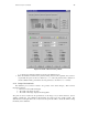
3. Bring up the calibration window by
pressing the Calibrate… menu button.
Fig. 4-4 shows the calibration dialog
window (the figure shows the dialog after
an image has been captured and processed).
4. Determine the appropriate characteristics of the camera imagers and enter them into the four
boxes in the middle of the dialog. If you have one of the Videre Design stereo heads, check the
appropriate box and the parameters are loaded automatically.
5. Acquire five stereo pairs of the calibration object at different rotations and translations. Try to
avoid views that differ by a simple translation, as they are less informative than views with
variation in rotation. As shown in Fig 4-4, there is a tab control that shows only one pair at a
time; choose a tab to select another pair. To capture the current video feed into a stereo pair box,
simply press the capture button. You can also save and load images to and from disk using the
load and save buttons.
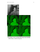
6. Detect the corner features in all views by pressing the features button in the lower bar of
buttons. This cycles through all the images, displaying the corners in green as they are detected.
If the feature finder fails on an image, please re-capture the image and redetect the features.
When redetecting features for a single stereo pair, use the features button in the stereo pair
box.
7. Compute the calibration parameters (intrinsics, extrinsics) and rectification matrices by pressing
the calibrate button in the lower button bar. This operates in three phases:
a) Calibrates individual views using a planar model of the calibration object. The projection of
these model features is shown in red.
b) Calibrates all the views jointly using nonlinear optimization over all the intrinsic and
extrinsic parameters. This phase usually takes a few minutes, and when finished, the
projected model features are shown in yellow.
Figure 4-1 Checkerboard calibration object.