
User manual
Small Vision System User Manual 20
2.4 Stereo Processing and Parameters
In smallv, stereo processing takes place in conjunction with the input of stereo images. The basic
cycle is:
get stereo pair -> process pair -> display pair
The input is either from live video or the buffer (Sections 2.1 and 2.1.9). In freeze mode, the same pair is
processed continuously, so adjustments can be made in stereo parameters.
2.4.1 Stereo Function
Stereo processing is turned on by choosing Stereo from the Function drop list. The stereo
disparity image will appear in the right display. Stereo disparities are encoded by green: brighter green is
a higher disparity, and therefore closer to the cameras (see Section 2.4.4 for a technical description of
disparity).
Disparities represent the distance between the horizontal appearance of an object in the stereo images.
The stereo process interpolates this distance to 1/16 pixel, e.g., a disparity value of 45 represents a
displacement of 2 13/16 pixels. The maximum displacement currently supported is 80 pixels, so disparity
values range from 0 (no disparity) to 1280. Disparity values are returned as 16-bit (short) integers. The
values 0xFFFF and 0xFFFE are reserved for filtering results (Section 2.5)
If smallv is running on a Pentium MMX processor (MMX, PII, or PIII) then stereo processing is
much faster, taking advantage of the parallel data operations. The processor is queried and the MMX box
is checked if the instructions are available. You can turn the MMX processing on and off by toggling the
box. But, if your system does not have MMX instructions, you will not be able to turn it on.
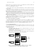
2.4.2 3D Transformation
A pixel in the disparity image represents range to an object. This range, together with the position of
the pixel in the image, determines the 3D position of the object relative to the stereo rig. SVS contains a
function to convert disparity values to 3D points. These points can then be displayed in a 3D viewer.
To take the current disparity image and display it in 3D, press the 3D Display button. An
OpenGL window will show the 3D points constructed from the disparity image, and you can change the
viewpoint of the window to see the 3D structure.
2.4.3 Calibration
For good stereo processing, the two images must be aligned correctly with respect to each other. The
process of aligning images is called calibration. Generally speaking, there are two parts to calibration:
internal calibration, dealing with the properties of the individual cameras and especially lens distortion;
and external calibration, the spatial relationship of the cameras to each other. Both internal and external
calibration are performed by an automatic calibration procedure described in Section 4. The procedure
needs to be performed when lenses are changed, or the cameras are moved with respect to each other.
From the internal and external parameters, the calibration procedure computes an image warp for
rectifying the left and right images. In stereo rectification, the images are effectively rotated about their
centers of projection to establish the ideal stereo setup: two cameras with parallel optical axes and
horizontal epipolar lines (see Fig. 2-2). Having the epipolar lines horizontal is crucial for correspondence
finding in stereo, as stereo looks for matches along horizontal scanlines.
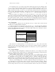
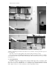
Figure 2-7 shows a pair of images of the calibration target taken with the MEGA-D stereo head and a
4.8 mm wide-angle lens. In the original images on the top, there is lens distortion, especially at the edges
of the image: notice the curve in the target. Also, the images are not aligned vertically.
The bottom pair is the result of calibrating the stereo head and then rectifying the two original
images. Now the images are aligned vertically, and all scene lines are straight in the images.
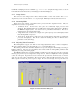
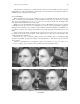
Figure 2-8 shows sample disparity images for uncalibrated and calibrated cameras. Without
calibration, it is impossible for the stereo algorithms to find good matches.