
User`s manual


STH-MDCS USER’S MANUAL 2001 VIDERE DESIGN
6
3 Hardware Overview
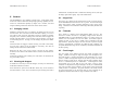
Figure 3-1 shows the hardware configuration of the STH-MDCS/-C.
The imager module has a milled Delrin frame that rigidly holds two
megapixel imagers, separated by a fixed distance of 9 cm. Lens mounts are
an integral part of the frame, and standard C-mount lenses are screwed into
these holders. There is an IR cutoff filter, with a knee at approximately 680
nm, permanently mounted inside the lens holder. See Section 4 for
appropriate lens characteristics.
The interface module is mounted on the back of the stereo head. One 1394
port is placed at the back of the module; it is inset so that the 1394 plug
does not stick out from the device.
A status LED indicates video imager activity. It will turn on when the
device is powered and connected to an IEEE 1394 card on the host
computer. The LED will begin flashing as soon as images are being
acquired by the host computer, at ½ the frame rate. Changing the video
modes (frame size, decimation) will cause the frame rate to change, and this
will be reflected in the LED flash rate.
There are no user-settable switches on the STH-MDCS/-C.
3.1 Hardware Schematic
Figure 3-2 shows the design of the internal hardware of the STH-MDCS/-
C. In the stereo imager module, two CMOS imagers, each of size 1280 x
1024 pixels, digitize incoming light into a digital stream. The imagers
operate in progressive mode only, that is, each line is output in succession
from the full frame.
The maximum video rate is 12 megapixels per second from each imager.
The imagers are synchronized to a common clock, so that the corresponding
pixels from each imager are output at precisely the same time. Special
interlace electronics convert the individual streams into a single pixel-
interlaced stream at 24 MHz. The interlaced stream contains one byte from
the left imager, then the corresponding byte from the right imager, then the
next byte from the right imager, and so on.
The interlaced video stream is transferred to the 1394 interface module,
which communicates to the host PC over a 1394 digital cable. The module
also accepts commands from the host PC over the cable, and uses these
commands to control imaging modes such as exposure or subwindowing.
The 1394 interface module can communicate at the maximum 1394 data
rate, 400 MBps.
3.2 Frame Formats and Rates
The 1394 interface electronics supports a maximum rate of 24 megapixels
per second. At this rate, there is no need for large buffer memories to hold
video data on the stereo device. The STH-MDCS/-C conforms to the IIDC
version 1.30 camera specification. Frame rates and frame sizes are set by
this standard. The STH-MDS/-C implements the formats shown in Table 1.
The Digital Camera Specification was set up with monocular cameras in
mind. To conform to this specification, the STH-MDS/-C uses the YUV
Figure 3-1. Physical layout of the STH-MDCS/-C stereo head.
Left
C-mount
lens
1394 port
on bac
k
Right
C-mount
lens
LED
indicato
r