ULISSE MAXI NETCAM Unit for large-size zoom lenses for network cameras EN English - Instructions manual IT Italiano - Manuale di istruzioni FR Français - Manuel d’instructions DE Deutsch - Bedienungslanleitung
ULISSE MAXI NETCAM Unit for large-size zoom lenses for network cameras EN English - Instructions manual
Contents ENGLISH 1.1 Typographical conventions................................................................................................................................... 7 2 Notes on copyright and information on trademarks................................................... 7 3 Safety rules..................................................................................................................... 7 4 Identification...........................................................................
EN - English - Instructions manual 7.2.4 Connection of the ethernet cable....................................................................................................................................22 7.2.5 Fixing the top unit..................................................................................................................................................................23 7.2.1 Counterweights installation................................................................................
15 Technical data............................................................................................................. 40 16 Technical drawings..................................................................................................... 42 5 Instructions manual - English - EN 15.1 General.....................................................................................................................................................................40 15.2 Mechanical....................
6 EN - English - Instructions manual
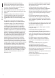
1 About this manual 1.1 Typographical conventions DANGER! High level hazard. Risk of electric shock. Disconnect the power supply before proceeding with any operation, unless indicated otherwise. DANGER! Hot surface. Avoid contact. Surfaces are hot and may cause personal injury if touched. DANGER! Mechanical hazard. Risk of crushing or shearing. WARNING! Medium level hazard. This operation is very important for the system to function properly.
EN - English - Instructions manual • Never, under any circumstances, make any changes or connections that are not shown in this handbook. Improper use of the appliance can cause serious hazards, risking the safety of personnel and of the installation. • Use only original spare parts. Non-original spare parts could cause fire, electrical discharge or other hazards.
• Do not allow children or unauthorised people to use the appliance. • Only skilled personnel should carry out maintenance on the device. When carrying out maintenance, the operator is exposed to the risk of electrocution and other hazards. • Use only the accessories indicated by the manufacturer. Any change that is not expressly approved by the manufacturer will invalidate the guarantee. • The unit has been made for connection using a 3-pole cable.
EN - English - Instructions manual 4 Identification 4.2 Product markings 4.1 Product description and type designation ULISSE MAXI NETCAM was specifically designed for external IP video surveillance applications, in combination with modern SD, HD and Megapixel cameras. A special feature on this device is the ability to easily control, via the network, all the camera's pan & tilt functions (including wiper, preset and setup) with a vast majority of the VMS on the market.
6 Preparing the product for use All other parts must not be disassembled or tampered (excepting for mounting and maintenance operations according the present manual). 6.1 Safety precautions before use The appliance includes moving parts. Make sure that the unit is positioned where it is inaccessible under normal operating conditions. Attach the warning label supplied with the appliance, placing it near the unit so that it can be seen easily.
6.4.1.2 Attachment with a pole support (optional) The column support allows the internal passage of the connection cables. 6.4.1 Attaching the support There are two kinds of support, choose the most suitable one for your installation and follow all the instructions given in this section. Take special care when attaching and fastening down the apparatus.
7 Assembling and installing This is a Class A product. In a domestic environment this product may cause radio interference. In this case the user may be required to take adequate measures. Only network cameras with specific technical characteristics can be installed (7.1.1 Camera's required features for installation, page 13). 7.1 Assembly Mount the sunshield to the housing with the four screws and 4+4 washers provided as standard. 7.1.
EN - English - Instructions manual 7.1.2 Assembling the camera and motorised lenses The correct device working, in the stated temperature range, is guaranteed with the use of camera and lens with temperature from -10°C up to +60°C. Position the lens on the slide (02) interposing the plastic spacer (01), and fasten the whole assembly by means of the nylon washer (03)and the 1/4" screw (04). If necessary, use the additional spacers to correctly position the camera and lens.
7.1.2.3 Positioning of the H-20 spacer in the inner slide It is possible to fasten the H-20 spacer (02) to the lens. Interpose a plastic spacer (01) of the required thicknessand fix it by means of washer and screw (03). Insert the 2 desiccant salt sachets (01) in the position indicated in the illustration, after having taken them out from the transparent packaging and folding them in half. Fasten the sachets by means of the plates (02) and screws supplied (03). 03 02 01 01 02 03 Fig. 13 Fig.
EN - English - Instructions manual 7.1.3 Connection of the camera and motorised lens 7.1.3.2 Connector for camera/motorised lenses 7.1.3.1 Motorised lens PTZ board All connections illustrated below should be made only and exclusively by expert installers who should comply with all the wiring and power supply specifications for the devices. The following is a description of the electronics board inside the housing, which controls all functions of the motorised lens.
In the case of lenses with reverse polarity motors, connect as shown in the figure. M M + Before powering the Pan & Tilt, set the lens power voltage using DIP1. FOCUS + FOCUS IRIS + IRIS ZOOM + ZOOM - + + Instructions manual - English - EN M 7.1.3.3 Adjustment of the supply voltage of the lens motors CN2 DIP1 Fig. 19 CN2. In the case of lenses with common wire motors, it is necessary to enable the corresponding menu option (9.1.13 Camera Parameters, page 33).
7.2 Installation EN - English - Instructions manual Do not make any changes or install connections that are not included in this handbook. Failure to follow the connection instructions that are given in the handbook may create serious safety hazards for people and for the installation. 7.2.1 Connecting the cables to the base Insert the cables into the cable glands and, holding the base at about 20cm from the support, lock the cable glands with a torque wrench setting of 5Nm.
7.2.2 Fixing the base to the support Use the screws and the washers supplied with the base. The following is a description of the connector board located inside the P&T base. Ethernet CN4 CN7 02 01 03 06 05 CN1 04 Fig. 27 Fig. 30 02 01 03 06 05 04 Fig. 28 Align the 3 notches on the base with those on the support as shown in the following figure. 7.2.3.
EN - English - Instructions manual When commencing installation make sure that the specifications for the power supply for the installation correspond with those required by the device. All signal cables must be grouped together by means of a strap. Make sure that the power source and connecting cables are suitable for the power consumption of the system. Earth cable should be about 10mm longer than the other two, so that it will not be disconnected accidentally if pulled.
7.2.3.2 Connection of the 24Vac power supply line 7.2.3.3 Connection of the 120/230Vac power supply line To connect the power supply line use the appropriate junction-box (UPTJBUL). For further information, refer to the product use and installation manual. Power the device with an SELV type, 24Vac, 8A isolated source derived from a double isolation UL Listed transformer specially protected in output. Alternatively, use the UPTIRPS120 power supply and control kit.
7.2.3.4 Connection of the alarm inputs, of the twilight switch and of the relays EN - English - Instructions manual The installation is type TNV-1, do not connect it to SELV circuits. In order to reduce the risk of fire, only use cable sizes greater than or equal to 26AWG (0.13mm²).
7.2.5 Fixing the top unit 7.2.1 Counterweights installation Fully fasten the counterweights to the casing by means of the M5 screws and washers supplied as standard. Instructions manual - English - EN Inside the bottom cover there is a sachet containing desiccant that is used to prevent moisture formation in the base and near the connector boards. Remove the sachet during installation. Attach the top unit (01) to the base (02) using the attachment screws (03), supplied with the corresponding seals (04).
EN - English - Instructions manual Fasten the safety grub screws of the counterweights’ pins. 7.2.1 Counterweights adjustment For the correct operation of the pan & tilt function, the counterweights have to be adjusted. Loosen the weight’s locking screws (01). Move the weights to the desired position. This must be the same for both weights, to help with this, use the reference holes (02) at the back of the counterweights. Fig.
7.2.2 Fastening of the wiper blade Insert the blade in the wiper shaft. 7.3 Configuration Fig. 47 Fig. 45 7.3.1 Configuration of the dip-switches Position the blade in the stop position. Once the configuration cover is opened the dipswitches will appear as shown in the figure. Fig. 48 7.3.2 DIP1 configuration When the dip-switch rocker is up it represents the value 1 (ON). When the dip-switch rocker is down it represents the value 0 (OFF). Fig.
8 Switching on EN - English - Instructions manual Make sure that the unit and other components of the installation are closed so that it is impossible to come into contact with live parts. During normal operation the surface of the illuminator can reach high temperatures. Do not, therefore, allow direct contact and position the appliance where it is inaccessible to unauthorised persons. Before touching switch off the illuminator and allow to cool for a minimum period of 10 minutes.
9 Configuration Browsers supported: Microsoft Internet Explorer, Google Chrome, Mozilla Firefox. The MAC Address is contained on the label that is on the CPU board. 9.1.1 First access For proper operation, the pan & tilt must be configured in relation to the installed camera. Instructions manual - English - EN During the first connection assign an address other than 192.168.0.100. 9.1 Web interface The required parameters are: • The IP protocol used to communicate with the camera.
The virtual keyboard contains the following controls: If you log in successfully, the Pan & Tilt management interface will appear. • Speed selector: It selects the speed of the pan & tilt movements. EN - English - Instructions manual 9.1.2 Home Fig. 54 • Zoom wide/Zoom tele Fig. 55 • Focus far/Focus near/Auto focus Fig. 52 9.1.3 User Controls To control Pan & Tilt movement through the browser, select the User control entry. A new window will open with a virtual keyboard to enter commands. Fig.
9.1.6 Network Configuration From menu entry Device Parameters it is possible to set the name of the pan & tilt and view other additional information. From menu entry Network Configuration it is possible to change the setting of the Pan & Tilt network. It is possible to decide whether the device requires an address assigned statically, dynamically with DHCP or self-generated. The device supports the Internet Protocol (IP) in version 4.
EN - English - Instructions manual It is also possible to specify if the device needs to be synchronised with an external NTP (Network Time Protocol) server. 9.1.8 Movement Parameters • NTP -> DISABLED: Select this option if you do not wish to synchronise date and time of the device. From menu entry Movement Parameters it is possible to control, via web, all Pan & Tilt parameters that used to be configured through an On-Screen Menu in previous models.
9.1.8.1 Autopan 9.1.9 Preset Parameters In the Autopan subsection it is possible to specify the preset autopan start and end.. From menu entry Preset Parameters a number of parameters relative to the presets can be configured: • Ramp type: This allows you to select the Pan & Tilt accelerations. • Speed Of Movements (Default): The speed used in autopan and patrol operations. Fig. 66 9.1.8.2 Patrol • Impose default speed: The default speed will also be set as the scanning speed for all presets.
EN - English - Instructions manual 9.1.11 Digital I/O 9.1.12 Washer In the Digital I/O tab it is possible to configure the digital channels available in Pan & Tilt. What follows is a brief description of the configurable parameters for each digital input. The Pan & Tilt wash pump is configured in the Washer tab where it is possible to associate a preset to the washing operation, set the duration of washing and specify the wiper on/off delay. • Alarm ID: Field used to select the desired digital input.
9.1.14 Tools The parameters of the IP camera that were set at first start up can be edited in the Camera Parameters section. In the Camera Parameters section it is possible to specify zoom factor and precision of the zoom position. This section also displays the data for the different ONVIF profiles exported from the camera. From menu entry Tools it is possible to re-set the predefined values for the entire configuration of Pan & Tilt or only for a number of specific sections.
9.2 VTTunnel EN - English - Instructions manual 9.1.15 Factory Default To restore the factory settings relative to the network, user access and camera configuration follow this procedure: The application works only with Java™. If Java™ is not installed download the latest version at www.java.com. • Turn on the unit. • Open the cover of the dip-switches. The application can be connected only to the first interface of the network. Leave only the network cable connected to the pan & tilt.
10 Accessories 10.1.1 Connecting the pump If the pan & tilt is fitted with a wiper, it can also have an external pump supplying water to clean the glass. As shown in the picture, the spray to clean the glass is outside the pan & tilt. The diagram shows: • O1 - C1: Clean contact for starting the water pump. O1 C1 Fig. 78 Fig. 77 Once the command has been sent the pan & tilt positions itself with the glass facing the spray (9.1.3 User Controls, page 28).
EN - English - Instructions manual 11 Instructions for exceptional operation Turn off the P&T. Switch the dip switches to OFF. 11.1 How to switch from ONVIF communication mode to RS-485 (telemetry) mode The P&T is by default set to communicate via ONVIF protocol. 11.2 How to change communication mode Turn off the P&T. Set the dip switches (7.3 Configuration, page 25).
12 Maintaining and cleaning 12.1 Maintaining Maintenance must be carried out by personnel trained to operate on electrical circuits. Fuse F1 Fuse F2 24Vac, 50/60Hz F 6.3A L 250V 5x20 T 8A H 250V 5x20 120Vac, 50/60Hz F 6.3A L 250V 5x20 T 4A H 250V 5x20 230Vac, 50/60Hz F 6.3A L 250V 5x20 T 2A H 250V 5x20 Instructions manual - English - EN Before doing any technical work on the device, disconnect the power supply. Fuses replacement Voltage Tab. 8 12.1.
EN - English - Instructions manual 12.2 Cleaning Die Schwenk-Neige-Köpfe bedürfen keiner aufwendigen Wartung. Für die Reinigung des Gerätes Neutralreiniger und nicht schleifende Tücher benutzen. Es sei daran erinnert, dass die Einrichtung wasserundurchlässig ist. 12.2.1 Window and plastic cover cleaning (PC) Avoid ethyl alcohol, solvents, hydrogenated hydrocarbide, strong acid and alkali. Such products may irreparably damage the surface.
14 Troubleshooting Ask for assistance from skilled personnel if: • There is noticeable deterioration in performance of the unit. • The unit does not work properly, even though all the instructions in this handbook have been followed. Problem The device is off and shows no signs of life. Cause Wiring error, blown fuse. Solution Make sure the connections are correct. Check the continuity of the fuses and if one is blown replace it using the size as indicated in the table.
EN - English - Instructions manual 15 Technical data The installation is type TNV-1, do not connect it to SELV circuits. In order to reduce the risk of fire, only use cable sizes greater than or equal to 26AWG (0.13mm²). 15.1 General 15.2 Mechanical Cable glands: 3xM16 Horizontal rotation: continuous Vertical rotation: from +45° to -20° Horizontal speed (variable): from 0.02° up to 20°/s Tilt speed (variable): from 0.
15.6 Environment Suitable for use with network cameras Indoor/Outdoor Input voltage: -- 230Vac, 50/60Hz, 100W Operating temperature (with heater): -10° (14°F)/+60°C (140°F) -- 24Vac, 50/60Hz, 100W Resistant to salty fog (EN50130-5, EN60068-2-52) -- 120Vac, 50/60Hz, 100W Surge immunity: up to 2KV line to line, up to 4KV line to earth (Class 4) Current consumption: -- 230Vac, 0.4A -- 24Vac, 4A -- 120Vac, 0.8A Camera power supply: 12Vdc (800mA) 15.
16 Technical drawings 432 113 B 152 95 USABLE AREA 144 160 A USABLE AREA 105 EN - English - Instructions manual The dimensions of the drawings are in millimetres. A-A B A B-B 135 400 173 650 20° 45° 650 650 790 R410 258 Ø 780 Fig. 87 42 ULISSE MAXI NETCAM.
432 113 B 152 USABLE AREA 144 USABLE AREA Instructions manual - English - EN 160 A A-A B A B-B 135 400 173 650 20° 45° 70 650 650 790 R410 258 Ø 780 Fig. 88 ULISSE MAXI NETCAM, version for thermal cameras.
Headquarters Italy Videotec S.p.A. UK Representative office Via Friuli, 6 - I-36015 - Schio (VI) Italy Tel. +39 0445 697411 - Fax +39 0445 697414 Email: info@videotec.com Tel./Fax +44 01353 775438 (Sales) Tel. +44 0113 815 0047 (Technical support) Tel. +44 0113 815 0031 (Orders/Shipping dept.) Email: info.uk@videotec.com France Videotec France S.à.r.l. Asia Pacific Videotec (HK) Ltd Voie du Futur, Zac des Portes - 27100 - Val-de-Reuil, France Tel. +33 2 32094900 - Fax +33 2 32094901 Email: info.
ULISSE MAXI NETCAM Unità per obiettivi di grandi dimensioni per telecamere network IT Italiano - Manuale di istruzioni
Sommario ITALIANO 1 Informazioni sul presente manuale.............................................................................. 7 1.1 Convenzioni tipografiche...................................................................................................................................... 7 4.1 Descrizione e designazione del prodotto......................................................................................................10 4.2 Marcatura del prodotto....................................
IT - Italiano - Manuale di istruzioni 7.2.4 Collegamento del cavo di rete ethernet........................................................................................................................22 7.2.5 Fissaggio dell’unità superiore............................................................................................................................................23 7.2.1 Montaggio dei contrappesi................................................................................................
15 Dati tecnici.................................................................................................................. 40 16 Disegni tecnici............................................................................................................ 42 5 Manuale di istruzioni - Italiano - IT 15.1 Generale..................................................................................................................................................................40 15.2 Meccanica.............
6 IT - Italiano - Manuale di istruzioni
1 Informazioni sul presente manuale 1.1 Convenzioni tipografiche PERICOLO! Pericolosità elevata. Rischio di scosse elettriche. Prima di eseguire qualsiasi operazione assicurarsi di togliere tensione al prodotto, salvo diversa indicazione. PERICOLO! Superficie calda. Evitare il contatto. Le superfici sono calde e potrebbero causare danni alla persona in caso di contatto. PERICOLO! Pericolo di natura meccanica. Rischio di schiacciamento o cesoiamento. ATTENZIONE! Pericolosità media.
IT - Italiano - Manuale di istruzioni • Non effettuare per nessun motivo alterazioni o collegamenti non previsti in questo manuale. L'uso di apparecchi non idonei può portare a gravi pericoli per la sicurezza del personale e dell'impianto. • Utilizzare solo parti di ricambio originali. Pezzi di ricambio non originali potrebbero causare incendi, scariche elettriche o altri pericoli.
• Non permettere l’uso dell’apparecchio a bambini o personale non autorizzato. • L’apparecchio si considera disattivato soltanto quando l’alimentazione è stata tolta e i cavi di collegamento con altri dispositivi sono stati rimossi. • Utilizzare solo gli accessori indicati dal costruttore. Qualsiasi cambiamento non espressamente approvato dal costruttore fa decadere la garanzia. • L’unità è stata realizzata per essere collegata con cavo tripolare.
4 Identificazione 4.2 Marcatura del prodotto IT - Italiano - Manuale di istruzioni 4.1 Descrizione e designazione del prodotto ULISSE MAXI NETCAM è stato creato appositamente per applicazioni esterne di videosorveglianza IP, in combinazione con le moderne telecamere SD, HD e Megapixel.
6 Preparazione del prodotto per l'utilizzo Tutte le altre parti dell'unità non devono essere smontate o manomesse (eccetto per operazioni di montaggio e manutenzione previste nel presente manuale). 6.1 Precauzioni di sicurezza prima dell'utilizzo L'apparecchiatura comprende parti mobili. Assicurarsi che l'unità venga posizionata in un'area non accessibile durante le normali condizioni di funzionamento.
6.4 Lavoro preparatorio prima dell’installazione 6.4.1.2 Fissaggio con supporto a colonna (opzionale) Il supporto a colonna permette il passaggio interno dei cavi di collegamento. Esistono due tipi di supporti, scegliere il supporto più adatto all'installazione e seguire tutte le indicazioni riportate in questo capitolo. Porre particolare attenzione ai sistemi di fissaggio dell'apparecchiatura.
7 Assemblaggio e installazione L'assemblaggio e l'installazione vanno eseguiti solo da personale qualificato. Possono essere installate solamente telecamere di rete con determinate caratteristiche tecniche (7.1.1 Caratteristiche della telecamera necessarie per l'installazione, pagina 13). 7.1.1 Caratteristiche della telecamera necessarie per l'installazione • Si possono montare solo telecamere con porta di comunicazione ethernet di tipo 100 baseTx.
IT - Italiano - Manuale di istruzioni 7.1.2 Montaggio telecamera e ottiche motorizzate Il corretto funzionamento dell’apparecchiatura, nel range temperatura indicato, é garantito con l’utilizzo di telecamera e ottica con temperatura da -10° a +60°C. Posizionare l’ottica sulla slitta (02) interponendo il distanziale in plastica (01) e fissare il tutto con la rondella in nylon (03) e la vite da 1/4" (04).
7.1.2.3 Posizionamento del distanziale H-20 nella slitta interna Connettere la telecamera e fissare la staffetta a L (Fig. 9, pagina 14). Inserire i 2 sacchetti di sali essiccanti (01) nella posizione indicata in figura, dopo averli tolti dalla confezione trasparente e piegati in due. Fissate i sacchetti tramite le piastrine (02) e viti in dotazione (03). Manuale di istruzioni - Italiano - IT È possibile fissare un distanziale H-20 (02) all’ottica.
7.1.3 Collegamento della telecamera e dell’ottica motorizzata 7.1.3.2 Connettore telecamera/ottiche motorizzate IT - Italiano - Manuale di istruzioni 7.1.3.1 Scheda ottiche motorizzate PTZ Tutti i collegamenti illustrati di seguito devono essere eseguiti solo da installatori esperti e devono essere rispettate tutte le specifiche di cablaggio e di alimentazione dei dispositivi.
Nel caso di ottiche con motori ad inversione di polarità, eseguire le connessioni come illustrato in figura. M M FOCUS + FOCUS IRIS + IRIS ZOOM + ZOOM - + + Prima di alimentare il brandeggio, impostare la tensione di alimentazione delle ottiche agendo sul DIP1. CN2 DIP1 Fig. 19 CN2. Nel caso di ottiche con motori a filo comune è necessario abilitare la relativa opzione nel menu (9.1.13 Parametri Camera, pagina 33). Eseguire le connessioni come illustrato in figura.
7.2 Installazione IT - Italiano - Manuale di istruzioni Non effettuare alterazioni o collegamenti non previsti in questo manuale. Il mancato rispetto delle indicazioni fornite nel manuale in merito ai collegamenti può portare a gravi pericoli per la sicurezza del personale e dell’impianto. 7.2.1 Collegamento dei cavi alla base Introdurre i cavi all’interno dei pressacavi e tenendo la base a circa 20cm dal supporto serrare i pressacavi con coppia pari a 5Nm.
7.2.2 Fissaggio della base al supporto Utilizzare le viti e le rondelle fornite con la base. Di seguito è descritta la scheda connettori presente all'interno della base del brandeggio. Ethernet Manuale di istruzioni - Italiano - IT Dopo aver posizionato la guarnizione (01), fissare la base (02) sul supporto (03) utilizzando le viti (04), le rondelle dentellate (05) e gli anelli per vite (06). 7.2.3 Collegamento della scheda connettori CN4 CN7 02 01 03 06 05 CN1 04 Fig. 27 Fig.
All’atto dell’installazione controllare che le caratteristiche di alimentazione fornita dall'impianto corrispondano a quelle richieste dal dispositivo. Tutti i cavi di segnale devono essere raggruppati con una fascetta. IT - Italiano - Manuale di istruzioni Controllare che le fonti di alimentazione ed i cavi di collegamento siano in grado di sopportare il consumo del sistema.
7.2.3.2 Collegamento della linea di alimentazione in 24Vac 7.2.3.3 Collegamento della linea di alimentazione in 120/230Vac Solo per i prodotti marcati UL destinati al mercato Nordamericano, utilizzare un trasformatore UL listed, in classe 2. Alimentare il dispositivo con una sorgente isolata di tipo SELV, 24Vac, 8A derivata da un trasformatore a doppio isolamento UL Listed opportunamente protetto in uscita. In alternativa utilizzare il kit di alimentazione e controllo UPTIRPS120.
7.2.3.4 Collegamento degli ingressi di allarme, dell'interruttore crepuscolare e dei relè IT - Italiano - Manuale di istruzioni L'installazione è di tipo TNV-1, non collegare a circuiti SELV. Per ridurre il rischio di incendio usare solamente cavi aventi dimensioni maggiori o uguali a 26AWG (0.13mm²). Tutti i cavi di segnale devono essere raggruppati con una fascetta.
7.2.5 Fissaggio dell’unità superiore 7.2.1 Montaggio dei contrappesi Fissare saldamente i contrappesi alla custodia tramite le viti M5 e le rondelle in dotazione. Manuale di istruzioni - Italiano - IT All’interno della calotta inferiore, è presente un sacchetto contenente i sali disidratanti, utile per evitare la formazione di umidità nella base ed in corrispondenza alle schede connettori. Rimuovere il sacchetto durante l’installazione.
Fissare i grani di sicurezza delle spine dei contrappesi. 7.2.1 Regolazione dei contrappesi IT - Italiano - Manuale di istruzioni Per il corretto funzionamento del brandeggio si rende necessario regolare i contrappesi. Allentare le viti di bloccaggio dei pesi (01). Spostare i pesi nella posizione desiderata. La posizione deve essere la stessa per entrambe i pesi, a tale scopo aiutarsi con i fori di riferimento (02) sul retro dei contrappesi. Fig.
7.2.2 Fissaggio della spazzola tergicristallo Inserire la spazzola nell’albero del tergicristallo. 7.3 Configurazione Manuale di istruzioni - Italiano - IT Prima di alimentare il dispositivo è necessario configurarlo correttamente tramite i dipswitch presenti all’interno dello sportellino di configurazione. Aprire lo sportellino svitando le viti come illustrato in figura. Fig. 47 Fig. 45 7.3.1 Configurazione dei dip-switch Mettere la spazzola nella posizione di riposo.
8 Accensione IT - Italiano - Manuale di istruzioni Assicurarsi che l'unità e gli altri componenti dell’impianto siano chiusi in modo idoneo a impedire il contatto con componenti sotto tensione. Durante il normale funzionamento la superficie dell'illuminatore può raggiungere temperature elevate. Evitare pertanto il contatto diretto e posizionare l’apparecchiatura in luogo non accessibile al personale non autorizzato.
9 Configurazione Alla prima connessione assegnare un indirizzo diverso da 192.168.0.100. Il MAC Address è riportato sull’etichetta presente sulla scheda CPU. 9.1.1 Primo accesso Per un corretto funzionamento, il brandeggio deve essere configurato in funzione della telecamera installata. I parametri necessari sono: Manuale di istruzioni - Italiano - IT Browser supportati: Microsoft Internet Explorer, Google Chrome, Mozilla Firefox. 9.
Nella tastiera virtuale si trovano i seguenti comandi: Se il login viene effettuato con successo verrà mostrata l'interfaccia di gestione del brandeggio. • Selettore velocità: Permette di selezionare la velocità dei movimenti del brandeggio. IT - Italiano - Manuale di istruzioni 9.1.2 Home Fig. 54 • Zoom wide/Zoom tele Fig. 55 • Focus far/Focus near/Auto focus Fig. 52 9.1.3 Controlli Utente Per controllare la movimentazione del brandeggio via browser, selezionare la voce Controlli Utente.
9.1.6 Configurazione Rete Alla voce del menu Parametri Dispositivo è possibile impostare il nome del brandeggio e visualizzare altre informazioni aggiuntive. Alla voce del menu Configurazione Rete è possibile cambiare l'impostazione di rete del brandeggio. È possibile decidere se il dispositivo debba avere un indirizzo assegnato staticamente, dinamicamente con DHCP o autogenerato. Il dispositivo supporta il protocollo Internet Protocol (IP) in versione 4.
È possibile inoltre specificare se il dispositivo debba sincronizzarsi con un server NTP (Network Time Protocol) esterno. IT - Italiano - Manuale di istruzioni • NTP -> DISABILITATO: Selezionare questa opzione se non si vogliono sincronizzare data e ora del dispositivo. • NTP -> DHCP: Selezionare questa opzione nel caso si vogliano sincronizzare data e ora del dispositivo con quelle di un server NTP (Network Time Protocol) indicato dal server DHCP.
9.1.8.1 Autopan 9.1.9 Parametri Preset Nella sottosezione Autopan e possibile specificare il preset di inizio e di fine dell'autopan. Alla voce del menu Parametri Preset sono configurabili alcuni parametri relativi ai preset: • Velocità Scan: La velocità in gradi al secondo con cui viene raggiunto un preset su richiesta esplicita dell'operatore. • Velocità Movimenti (Default): La velocità usata nelle operazioni di autopan e patrol. Fig. 66 9.1.8.
IT - Italiano - Manuale di istruzioni 9.1.11 I/O Digitali 9.1.12 Washer Nella scheda I/O Digitali è possibile configurare i canali digitali presenti nel brandeggio. Segue una breve descrizione dei parametri configurabili per ciascun ingresso digitale.
9.1.13 Parametri Camera 9.1.14 Strumenti I parametri della camera IP che sono stato impostati al primo avvio sono modificabili alla voce del menu Parametri Camera. Alla voce del menu Parametri Camera è possibile inoltre specificare il fattore di zoom e la precisione della posizione dello zoom. In questa sezione è possibile anche visualizzare i dati relativi ai diversi profili ONVIF esportati dalla camera.
9.2 VTTunnel 9.1.15 Factory Default Per ripristinare le impostazioni di fabbrica relative alla rete, all'accesso utenti e alla configurazione della camera seguire la procedura: L'applicativo funziona solo con Java™. Se Java™ non è stato precedentemente installato scaricare l’ultima versione dal sito www.java.com. IT - Italiano - Manuale di istruzioni • Accendere l'unità. • Aprire lo sportellino dei dip-switch. L’applicativo può collegarsi solo alla prima interfaccia di rete attiva.
10 Accessori 10.1.1 Collegamento della pompa Il brandeggio, se provvisto di tergicristallo, può essere dotato anche di una pompa esterna che fornisce acqua per la pulizia del vetro. Come indicato in figura, lo spruzzo è in posizione esterna rispetto al brandeggio. Nello schema sono indicati: • O1 - C1: Contatto pulito per attivazione della pompa dell’acqua. O1 C1 Fig. 78 Fig. 77 Quando si invia il comando il brandeggio si posiziona con il vetro di fronte allo spruzzo (9.1.
IT - Italiano - Manuale di istruzioni 11 Istruzioni di funzionamento eccezionale Spegnere il brandeggio. Portare su OFF i dip-switch illustrati in figura. 11.1 Modifica della modalità di comunicazione (da protocollo ONVIF a telemetria seriale) Il brandeggio è nativamente configurato per comunicare via protocollo ONVIF. 11.2 Procedura di modifica della modalità di comunicazione Spegnere il brandeggio. Settare i dip-switch (7.3 Configurazione, pagina 25).
12 Manutenzione e pulizia Prima di effettuare interventi tecnici sull’apparecchio togliere l’alimentazione elettrica. La manutenzione deve essere eseguita solo da personale qualificato ad intervenire su circuiti elettrici. 12.1.1 Sostituzione dei fusibili Fusibile F1 Fusibile F2 24Vac, 50/60Hz F 6.3A L 250V 5x20 T 8A H 250V 5x20 120Vac, 50/60Hz F 6.3A L 250V 5x20 T 4A H 250V 5x20 230Vac, 50/60Hz F 6.3A L 250V 5x20 T 2A H 250V 5x20 Manuale di istruzioni - Italiano - IT 12.
12.2 Pulizia IT - Italiano - Manuale di istruzioni I brandeggi non necessitano di particolare manutenzione. Per la pulizia del dispositivo utilizzare detergenti neutri e panni non abrasivi. Si ricorda che il dispositivo è impermeabile. 12.2.1 Pulizia del vetro e delle parti in plastica (PC) Evitare alcool etilico, solventi, idrocarburi idrogenati, acidi forti e alcali. L’utilizzo di detti prodotti danneggia in modo irreparabile la superficie trattata.
Problema Richiedere l’intervento di personale qualificato quando: Non è possibile collegarsi alla telecamera. Causa Errato collegamento della telecamera. Soluzione Verificare i collegamenti della telecamera. Problema Durante l’accensione il brandeggio rimane bloccato. Causa La temperatura ambiente è molto bassa. Soluzione Attendere il termine della procedura di preriscaldamento. Problema Non è possibile controllare il brandeggio. Causa Errata configurazione della linea di comunicazione.
15 Dati tecnici IT - Italiano - Manuale di istruzioni L'installazione è di tipo TNV-1, non collegare a circuiti SELV. Per ridurre il rischio di incendio usare solamente cavi aventi dimensioni maggiori o uguali a 26AWG (0.13mm²). 15.1 Generale 15.2 Meccanica Pressacavi: 3xM16 Rotazione orizzontale: continua Rotazione verticale: da +45° a -20° Velocità orizzontale (variabile): da 0.02° fino a 20°/s Velocità verticale (variabile): da 0.
15.3 Elettrico 15.6 Ambiente Adatto all’impiego con telecamere network Interno/Esterno Tensione di ingresso: Temperatura di esercizio (con riscaldamento): -10°C /+60°C -- 230Vac, 50/60Hz, 100W -- 24Vac, 50/60Hz, 100W -- 230Vac, 0.4A -- 24Vac, 4A -- 120Vac, 0.8A Alimentazione telecamere: 12Vdc (800mA) 4 ingressi di allarme autoalimentati Immunità agli impulsi: fino a 2KV tra linea e linea, fino a 4KV tra linea e terra (Classe 4) 15.
16 Disegni tecnici Le dimensioni dei disegni sono espresse in millimetri. 432 113 152 AREA UTILE 105 144 AREA UTILE 95 A 160 IT - Italiano - Manuale di istruzioni B A-A B A B-B 135 400 173 650 20° 45° 650 650 790 R410 258 Ø 780 Fig. 87 42 ULISSE MAXI NETCAM.
432 113 B 152 AREA UTILE AREA UTILE 144 160 A Manuale di istruzioni - Italiano - IT A-A B A B-B 135 400 173 650 20° 45° 70 650 650 790 R410 258 Ø 780 Fig. 88 ULISSE MAXI NETCAM, versione per telecamere termiche.
Headquarters Italy Videotec S.p.A. UK Representative office Via Friuli, 6 - I-36015 - Schio (VI) Italy Tel. +39 0445 697411 - Fax +39 0445 697414 Email: info@videotec.com Tel./Fax +44 01353 775438 (Sales) Tel. +44 0113 815 0047 (Technical support) Tel. +44 0113 815 0031 (Orders/Shipping dept.) Email: info.uk@videotec.com France Videotec France S.à.r.l. Asia Pacific Videotec (HK) Ltd Voie du Futur, Zac des Portes - 27100 - Val-de-Reuil, France Tel. +33 2 32094900 - Fax +33 2 32094901 Email: info.
ULISSE MAXI NETCAM Unité pour objectifs de grandes focales pour caméras network FR Français - Manuel d’instructions
Sommaire FRANÇAIS 1 À propos de ce mode d’emploi...................................................................................... 7 1.1 Conventions typographiques.............................................................................................................................. 7 4.1 Description et désignation du produit...........................................................................................................10 4.2 Marquage du produit.......................................
7.2.4 Branchement du câble de réseau ethernet..................................................................................................................22 7.2.5 Montage de la partie supérieure......................................................................................................................................23 7.2.1 Montage du contrepoids....................................................................................................................................................
14 Troubleshooting......................................................................................................... 39 15 Données techniques................................................................................................... 40 16 Dessins techniques..................................................................................................... 42 5 Manuel d'instructions - Français - FR 15.1 Généralités...........................................................................
6 FR - Français - Manuel d'instructions
1 À propos de ce mode d’emploi Avant d’installer et d’utiliser cet appareil, veuillez lire attentivement ce mode d’emploi. Conservez-le à portée de main pour pouvoir vous y reporter en cas de besoin. 1.1 Conventions typographiques DANGER! Surface à température élevée. Evitez le contact. La température des surfaces est élevée et leur contact peut provoquer des blessures corporelles. DANGER! Danger mécanique. Risque d’écrasement ou de cisaillement. ATTENTION! Risque moyen.
• Ne procéder sous aucun prétexte à des modifications ou des connexions non prévues dans ce manuel. L'utilisation d’appareils non adéquats peut comporter des dangers graves pour la sécurité du personnel et de l’installation. FR - Français - Manuel d'instructions • Utiliser uniquement des pièces de rechange d’origine. Les pièces non d’origine peuvent être source d’incendies, de choc électrique ou autres.
• Ne pas laisser l'appareil à portée des enfants ou de personnes non autorisées. • L’appareil ne doit être considéré comme désactivé qu'avec l'alimentation sectionnée et les câbles de connexion aux autres dispositifs débranchés. • L'entretien du dispositif doit uniquement être effectué par un personnel qualifié. Durant les opérations d'entretien, l'opérateur est exposé au risque d'électrocution ou autres. • L'unité a été réalisée pour un branchement avec câble tri-polaire.
4 Identification 4.2 Marquage du produit FR - Français - Manuel d'instructions 4.1 Description et désignation du produit ULISSE MAXI NETCAM a été créé spécifiquement pour des applications externes de vidéosurveillance IP, en combinaison avec les caméras modernes SD, HD et Mégapixel.
6 Préparation du produit en vue de l’utilisation Toute modification non approuvée expressément par le fabricant entraînera l’annulation de la garantie. 6.1 Précautions de sécurité avant l’utilisation L'appareil comprend des parties mobiles: s'assurer que l'unité est positionnée dans une zone non accessible pendant le fonctionnement. Appliquer l'étiquette fournie avec l'appareil près de l'objet et en position visible. 6.2 Déballage et contenu 6.2.
6.4 Opérations à effectuer avant l’installation 6.4.1 Fixation du support 6.4.1.2 Fixation avec colonne de support (en option) Le support en colonne permet le passage interne des câbles de branchement. Parmi les 2 types de supports disponibles, choisir le plus adapté à l'installation et se conformer aux indications de ce chapitre. Accorder une attention particulière aux systèmes de fixation de l'appareil.
7 Assemblage et installation L’assemblage et l’installation doivent être effectués par un personnel qualifié. Seules les caméras de réseau ayant des caractéristiques techniques déterminées peuvent être installées (7.1.1 Caractéristiques des caméras necessaires pour l'installation, page 13). 7.1 Assemblage Fixer le toit pare-soleil au caisson au moyen des 4 vis et des 4+4 rondelles fournies. 7.1.
7.1.2 Montage caméras, systèmes optiques motorisés Positionner l’optique sur la glissière (02) en intercalant l’entretoise en plastique (01) et fixer le tout avec la rondelle en nylon (03) et la vis de 1/4" (04). Le fonctionnement correct, dans la gamme de température indiquée, est assuré avec l’utilisation de caméra et optique avec température de -10°C jusqu’à +60°C. Si nécessaire, utiliser les entretoises supplémentaires pour positionner correctement la caméra et l’optique.
7.1.2.3 Positionnement de l’entretoise H-20 dans la glissière interne Connecter la caméra et fixer l’étrier à L (Fig. 9, page 14). Il est possible de fixer une entretoise H-20 (02) au système optique. Interposer une entretoise en plastique (01) de l’épaisseur requise et le fixer avec rondelle et vis (03). 7.1.2.4 Sels déshydratants Introduire les 2 sachets de sels déshydratants (01) dans les positions indiquées sur la figure après les avoir retirés de leur emballage transparent et pliés en deux.
7.1.3 Branchement de la caméra et de l'optique motorisée 7.1.3.2 Connecteur caméra/optiques motorisées 7.1.3.1 Carte de connexions pour l'optique motorisée PTZ Tous les branchements illustrés ci-après doivent exclusivement être exécutés par des installateurs experts et toutes les spécifications de câblage et d'alimentation des dispositifs doivent être respectées.
Dans le cas d'optiques avec moteurs à inversion de polarité, effectuer les connexions comme indiqué dans la figure. M M FOCUS + FOCUS IRIS + IRIS ZOOM + ZOOM - + + Avant d'alimenter la tourelle, programmer la tension d’alimentation des optiques en agissant sur le DIP1. CN2 Fig. 19 DIP1 CN2. Fig. 22 Dans le cas d'optiques avec moteurs à fil commun, il faut valider l'option correspondante dans le menu ( 9.1.13 Paramètres Caméra, page 33). Effectuer les connexions comme indiqué dans la figure.
7.2 Installation N'effectuer des modifications ou connexions non prévues dans ce manuel. L’utilisation d’appareils inadéquats peut comporter des risques sérieux pour les appareils et la sécurité du personnel. 7.2.1 Connexion des câbles à la base Passer et serrer les câbles dans les presse-câbles en maintenant la base à environ 20cm du support avec un couple de 5Nm. Les presse-câbles sont prévus pour des câbles avec un diamètre compris entre 5 et 10mm.
7.2.2 Fixage de la base au support Utiliser les vis et les rondelles fournies avec la base. Après avoir installé la garniture (01), fixer la base (02) sur son support (03) au moyen des vis (04), des rondelles dentées (05) et des anneaux pour vis (06). 7.2.3 Connexion de la carte de connexion Voir plus bas la description de la carte de connexion qui se trouve à l'intérieur de la base de la tourelle. Ethernet CN4 02 01 Manuel d'instructions - Français - FR CN7 03 06 05 CN1 04 Fig. 27 Fig.
Contrôler que les sources d'alimentation et les câbles de branchement sont en mesure de supporter la consommation du système. Tous les câbles de signalisation doivent également être regroupés avec un collier. FR - Français - Manuel d'instructions Procéder exclusivement aux connexions de la base avec l'alimentation sectionnée et le dispositif de sectionnement ouvert. Le câble de terre doit être plus long des deux autres d'environ 10mm pour éviter tout détachement accidentel.
7.2.3.2 Connexion de la ligne d'alimentation en 24Vac 7.2.3.3 Connexion de la ligne d'alimentation en 120/230Vac Seulement pour les produits marqués UL destinés au marché de l'Amérique du Nord, utiliser un transformateur UL listed, en classe 2. Pour connecter la ligne d'alimentation utiliser le junction-box spécifique (UPTJB UL). Pour plus d'informations, se référer au manuel d'utilisation et d'installation du produit.
7.2.3.4 Branchement des entrées d'alarme, de l'interrupteur crépusculaire et des relais FR - Français - Manuel d'instructions L'installation est du type TNV-1, ne pas la connecter à des circuits SELV.
7.2.5 Montage de la partie supérieure 7.2.1 Montage du contrepoids La calotte inférieure contient un sachet de sels déshydratants permettant d'éviter la formation d'humidité dans la base et à hauteur des cartes des connecteurs. Retirer le sachet durant l'installation. Fixer solidement les contrepoids au caisson au moyen des vis M5 et des rondelles fournies.
Fixer les vis sans tête de sûreté des fiches des contrepoids 7.2.1 Réglage des contrepoids En vue d’un fonctionnement correct de la tourelle, il est nécessaire de régler les contrepoids. FR - Français - Manuel d'instructions Desserrer les vis de fixation des poids (01). Déplacer les poids dans la position désirée. La position des deux contrepoids doit être identique; utiliser les orifices repères (02) à l’arrière des contrepoids. Fig.
7.2.2 Fixation du balai essuie-glace Insérer le balai dans l’arbre de l’essuie-glace 7.3 Configuration Avant de mettre l'appareil sous tension, il est nécessaire de le configurer correctement au moyen des dip-switches installés derrière le panneau de configuration. Ouvrir le panneau de configuration en desserrant les vis comme indiqué sur la figure. Fig. 47 Placer le balai en position de repos. 7.3.
8 Allumage S'assurer que l'unité et les autres composants de l'installation soient fermés de façon à empêcher le contact avec les composants sous tension. FR - Français - Manuel d'instructions Durant le fonctionnement normal, la surface du projecteur peut atteindre des températures élevées. Éviter par conséquent tout contact direct et positionner l’appareil dans un endroit non accessible au personnel non autorisé.
9 Configuration À la première connexion, donner une adresse différente de 192.168.0.100. 9.1 Interface web 9.1.1 Premier accès Pour un fonctionnement correct, la tourelle doit être configurée en fonction la caméra installée. Logiciels de navigation supportés: Microsoft Internet Explorer, Google Chrome, Mozilla Firefox. Les paramètres nécessaires sont les suivants : L'adresse MAC est indiquée sur étiquette présente sur la carte CPU. • Le type d'optiques installées (motorisée, fixe ou intégrée).
9.1.2 Home FR - Français - Manuel d'instructions Si le login est effectué avec succès, on pourra voir l'interface de gestion de la tourelle. Sur le clavier virtuel, se trouve les commandes suivantes : • Sélecteur vitesse: Il permet de sélectionner la vitesse des mouvements de la tourelle. Fig. 54 • Zoom wide/Zoom tele Fig. 55 Fig. 52 • Focus far/Focus near/Auto focus 9.1.3 Contrôles Utilisateur Pour contrôler le mouvement de la tourelle par navigateur, sélectionner la mention Contrôle Utilisateur.
9.1.4 Paramètres Dispositif 9.1.6 Configuration Réseau A la mention du menu Paramètres Dispositif il est possible de configurer le nom de la tourelle et d'afficher d'autres informations supplementaire. A la mention du menu Configuration Réseau il est possible de changer la configuration de réseau de la tourelle. Il est possible de décider si le dispositif doit avoir une adresse attribuée de manière statique, dynamique avec DHCP, ou auto-générée.
Il est également possible de mentionner si le dispositif doit se synchroniser avec un serveur NTP (Network Time Protocol) externe. FR - Français - Manuel d'instructions • NTP -> DESACTIVE: Sélectionner cette option si on ne souhaite pas synchroniser date et heure du dispositif. • NTP -> DHCP: Sélectionner cette option au cas où on souhaite synchroniser date et heure du dispositif avec celles d'un serveur NTP (Network Time Protocol) indiqué par le serveur DHCP.
9.1.8.1 Autopan 9.1.9 Paramètres Preset Dans la sous-section Autopan il est possible d'indiquer le preset de début et de fin de l'autopan. A la mention du menu Paramètres Preset on peut configurer certains paramètres concernant les preset: • Vitesse De Scan: La vitesse en degrés à la seconde, avec laquelle un preset est atteint, sur demande explicite de l'opérateur. • Type de rampe: Permet de sélectionner les accélérations de la tourelle. Fig. 66 9.1.8.
9.1.11 I/O Digitaux 9.1.12 Washer Dans la carte I/O Digitaux il est possible de configurer les canaux digitaux présents dans la tourelle. Il y a ci-dessous une courte description des paramètres configurables pour chaque entrée numérique. La pompe pour le lavage de la tourelle est configurée dans la carte Washer, où il est possible d'associer un preset à l'opération de lavage, de configurer la durée du lavage du verre et d'indiquer le retard d'activation et de désactivation de l'essuie-glace.
9.1.13 Paramètres Caméra 9.1.14 Instruments Les paramètres de la caméra IP qui ont été configurés à la première mise en marche sont modifiables dans la section Paramètres Caméra. Dans la section Paramètres Caméra il est possible également d'indiquer le facteur de zoom et la précision de la position du zoom. Dans cette section, il est également possible de visualiser les données relatives aux différents profils ONVIF exportés par la chambre.
9.2 VTTunnel 9.1.15 Factory Default Pour restaurer les configurations d'usine relatives au réseau, à l'accès utilisateurs et à la configuration de la chambre, suivre la procédure : Le logiciel fonctionne seulement avec Java™. Si Java™ n'a pas été précédemment installé, télécharger la dernière version du site www.java.com. • Allumer l'unité. • Ouvrir le volet du commutateur DIP. Le logiciel peut se connecter seulement à la première interface de réseau actif.
10 Accessoires 10.1.1 Branchement de la pompe Les branchements illustrés ci-après doivent être exécutés seulement par du personnel qualifié. Il faut respecter scrupuleusement toutes les indications d'alimentation et de câblage, pour éviter de graves risques pour l'opérateur et l'annulation de la garantie. 10.1 Système de lavage La tourelle, si elle est munie d’un essuie-glace, peut aussi être équipée d’une pompe externe qui fournit l’eau pour le nettoyage de la glace.
FR - Français - Manuel d'instructions 11 Instructions de fonctionnement exceptionnel Éteindre la tourelle. Mettre sur OFF les dip-switch illustrés sur la figure. 11.1 Modification de la modalité de communication (depuis protocole ONVIF à télémétrie sérielle) La tourelle est configurée à l'origine pour communiquer par protocole ONVIF. 11.2 Procédure de modification de la modalité de communication Éteindre la tourelle. Régler les dip-swich (7.3 Configuration, page 25).
12 Entretien et nettoyage Sectionner l’alimentation électrique avant toute intervention technique sur l’appareil. 12.1 Entretien 12.1.1 Remplacement des fusibles Fusible F1 Fusible F2 24Vac, 50/60Hz F 6.3A L 250V 5x20 T 8A H 250V 5x20 120Vac, 50/60Hz F 6.3A L 250V 5x20 T 4A H 250V 5x20 230Vac, 50/60Hz F 6.3A L 250V 5x20 T 2A H 250V 5x20 Tab. 8 12.1.
12.2 Nettoyage Les tourelles n'exigent aucun entretien particulier. Pour le nettoyage de l'appareil, utiliser des détergents neutres et des chiffons non abrasifs. Le dispositif est imperméable. FR - Français - Manuel d'instructions 12.2.1 Entretiens de la vitre et des parties en plastique (PC) On doit éviter alcool éthylique, solvants, hydrocarbures hydro-génés, acides forts et alcali. L’emploi de ce type de produits abîme d’une façon irréparable la surface traitée.
Problème Demander l'intervention d'un personnel qualifié dans les cas suivants: Il n'est pas possible de se brancher à la caméra. Cause Branchement erroné de la caméra. Solution Vérifier les branchements de la caméra. Problème Durant la mise en service, la tourelle reste bloquée. Cause La température ambiante est très basse. Solution Attendre la fin de la procédure de préchauffage. Problème Il n'est pas possible de contrôler la tourelle.
15 Données techniques L'installation est du type TNV-1, ne pas la connecter à des circuits SELV. FR - Français - Manuel d'instructions Pour réduire les risques d’incendie, utiliser uniquement des câbles de dimensions égales ou supérieures à 26AWG (0.13mm²). 15.1 Généralités 15.2 Mécanique Presse-étoupes: 3xM16 Rotation horizontale: continu Rotation vertical: de +45° à -20° Vitesse horizontale (variable): de 0.02° à 20°/s Vitesse verticale (variable): de 0.
15.3 Électrique 15.6 Environnement Compatible avec des caméras network Intérieur/Extérieur Tension d’entrée: Température d'exploitation (avec chauffage): -10°/+60°C -- 230Vac, 50/60Hz, 100W -- 24Vac, 50/60Hz, 100W -- 120Vac, 50/60Hz, 100W Courant absorbé: -- 24Vac, 4A -- 120Vac, 0.8A Alimentation caméra: 12Vdc (800mA) 4 sorties d’alarmes auto-alimentées Protection contre les impulsions: jusqu’à 2KV entre deux lignes, jusqu’à 4KV entre ligne et terre (Classe 4) 15.
16 Dessins techniques Les dimensions des dessins sont exprimées en millimètres. 432 113 B 95 SURFACE UTILE 105 SURFACE UTILE 144 160 FR - Français - Manuel d'instructions 152 A A-A B A B-B 135 400 173 650 20° 45° 650 650 790 R410 258 Ø 780 Fig. 87 42 ULISSE MAXI NETCAM.
432 113 B 152 SURFACE UTILE SURFACE UTILE 144 160 A A-A B A B-B 400 Manuel d'instructions - Français - FR 135 173 650 20° 45° 70 650 650 790 R410 258 Ø 780 Fig. 88 ULISSE MAXI NETCAM, version pour caméras thermiques.
Headquarters Italy Videotec S.p.A. UK Representative office Via Friuli, 6 - I-36015 - Schio (VI) Italy Tel. +39 0445 697411 - Fax +39 0445 697414 Email: info@videotec.com Tel./Fax +44 01353 775438 (Sales) Tel. +44 0113 815 0047 (Technical support) Tel. +44 0113 815 0031 (Orders/Shipping dept.) Email: info.uk@videotec.com France Videotec France S.à.r.l. Asia Pacific Videotec (HK) Ltd Voie du Futur, Zac des Portes - 27100 - Val-de-Reuil, France Tel. +33 2 32094900 - Fax +33 2 32094901 Email: info.
ULISSE MAXI NETCAM Einheit für große Zoomobjektive für Netzwerk-Kameras DE Deutsch - Bedienungslanleitung
Inhaltsverzeichnis DEUTSCH 1 Allgemeines.................................................................................................................... 7 1.1 Schreibweisen............................................................................................................................................................ 7 2 Anmerkungen zum Copyright und Informationen zu den Handelsmarken.............. 7 3 Sicherheitsnormen........................................................................
7.2.4 Anschluss der Ethernet-Netz-Kabel.................................................................................................................................22 7.2.5 Montage der oberen Einheit..............................................................................................................................................23 7.2.1 Aufbau der Gegengewichte......................................................................................................................................
15 Technische Daten........................................................................................................ 40 15.1 Allgemeines............................................................................................................................................................40 15.2 Mechanik.................................................................................................................................................................40 15.3 Elektrik....................
6 DE - Deutsch - Bedienungslanleitung
1 Allgemeines Lesen Sie bitte vor dem Installieren und dem Verwenden dieses Gerätes die Bedienungsanleitung sorgfältig durch. Bewahren Sie sie zum späteren Nachschlagen auf. 1.1 Schreibweisen GEFAHR! Heiße Oberfläche. Nicht berühren. Die Oberflächen sind heiß und können bei Berührung zu Verbrennungen führen. GEFAHR! Gefahr mechanischer Natur. Quetsch- oder Scherkantengefahr. ACHTUNG! Mittlere Gefährdung.
• Unter keinen Umständen dürfen Veränderungen oder Anschlüsse vorgenommen werden, die in diesem Handbuch nicht genannt sind. Der Gebrauch ungeeigneten Geräts kann die Sicherheit des Personals und der Anlage schwer gefährden. DE - Deutsch - Bedienungslanleitung • Es dürfen nur Original-Ersatzteile verwendet werden. Nicht originale Ersatzteile können zu Bränden, elektrischen Entladungen oder anderen Gefahren führen.
• Kindern oder unbefugten Personen ist der Gebrauch des Gerätes zu untersagen. • Das Gerät gilt erst dann als deaktiviert, wenn die Stromversorgung ausgeschaltet und die Verbindungskabel zu den anderen Einrichtungen entfernt worden sind. • Die Wartung der Einrichtung ist Fachleuten vorbehalten. Während der Wartungsarbeiten ist die tätige Person der Gefahr von Stromschlägen und anderen Gefahren ausgesetzt. • Die Einheit ist dafür ausgelegt, über ein dreipoliges Kabel angeschlossen zu werden.
4 Identifizierung 4.2 Kennzeichnung des Produkts DE - Deutsch - Bedienungslanleitung 4.1 Beschreibung und Bezeichnung des Produktes ULISSE MAXI NETCAM wurde eigens für externe IP-Überwachungsanwendungen entworfen, in Kombination mit modernen SD, HD und MegapixelVideokameras.
6 Vorbereitung des Produktes auf den Gebrauch Jede vom Hersteller nicht ausdrücklich genehmigte Veränderung führt zum Verfall der Gewährleistungsrechte. 6.2.2 Inhalt Prüfen Sie, ob der Inhalt mit der nachstehenden Materialliste übereinstimmt: • Positionierungseinheit • Basis für Netzstromversorgung • Gegengewichte • Zubehör Schachtel: • Serieller Adapter 6.1 Sicherheitsvorkehrungen vor dem Gebrauch Das Gerät umfasst bewegliche Teile.
6.4 Auf die Installation vorbereitende Tätigkeiten 6.4.1.2 Befestigung mit Haltesäule (Optional) Der Ständer ermöglicht die interne Führung der Verbindungskabel. 6.4.1 Befestigung der Halterung Es gibt zwei Arten von Halterungen. Wählen Sie diejenige Halterung aus, die der Anlage am besten entspricht und befolgen Sie sämtliche Anweisungen aus diesem Kapitel. Besondere Aufmerksamkeit verlangen die Befestigungssysteme des Gerätes.
7 Zusammenbau und Installation Zusammenbau und Installation sind qualifizierten Fachleuten vorbehalten. Dies ist ein Produkt der Klasse A. Dieses Produkt kann im Wohnbereich Funkstörungen verursachen. In diesem Fall kann vom Betreiber verlangt werden, angemessene Maßnahmen durchzuführen. 7.1 Zusammenbau Die Haube mit den 4 Schrauben und den 4+4 Unterlegscheiben aus dem Lieferumfang am Gehäuse fixieren. 7.1.
7.1.2 Montage Kamera und motorisch bewegte Optiken Der richtige Anlagebetrieb ist, im angegebenen Temperaturbereich, nur mit der kamera- und Optik- Benutzung mit Temperatur bei -10° bis zu +60°C garantiert. Die Optik auf dem Schlitten (02) positionieren. Dabei den Abstandhalter aus Plastik zwischenlegen (01). Das Ganze mit der Unterlegscheibe aus Nylon (03) und der Schraube 1/4" (04) fixieren.
7.1.2.3 Positionierung des Abstandhalters H-20 im Innenschlitten Die Kamera zusammenstecken und die L-Bügel befestigen (Abb. 9, Seite 14). Es ist möglich einen H-20 Abstandhalter (02) an der Optik zu befestigen. Legen Sie einen Abstandhalter aus Plastik (01) in der gewünschten Dicke dazwischen und befestigen Sie ihn mit Unterlegscheibe und Schraube (03). 7.1.2.
7.1.3 Anschluss der Kamera und der motorisch bewegten Optik 7.1.3.2 Anschluss Kamera / motorisch bewegte Optik 7.1.3.1 Platine fur motorisch bewegte PTZ Optiken Alle nachstehend erläuterten Anschlüsse dürfen nur von Fachleuten ausgeführt werden und müssen den Anforderungen entsprechen, die hinsichtlich der Verdrahtung und Speisung der Einrichtungen bestehen. Nachstehend ist die elektronische Platine innerhalb des Gehäuses beschrieben, die alle Funktionen der motorisch bewegten Optik steuert.
Bei Optiken mit Motoren mit Politaritätsumschaltung sind die Anschlüsse so vorzunehmen, wie in der Abbildung gezeigt. M M M + Bevor die Stromversorgung des Schwenk-NeigeKopfes hergestellt wird, ist die Versorgungsspannung der Optiken mithilfe von DIP1 einzustellen. FOCUS + FOCUS IRIS + IRIS ZOOM + ZOOM - + + 7.1.3.3 Einstellung der Versorgungsspannung der Motoren der Optiken CN2 Bedienungslanleitung - Deutsch - DE Abb. 19 CN2.
7.2 Installation Unter keinen Umständen dürfen Änderungen oder Anschlüsse vorgenommen werden, die in diesem Handbuch nicht vorgesehen sind. Die Missachtung der Angaben, die das Handbuch zu den Anschlüssen macht, kann die Sicherheit von Personen und die Sicherheit der Anlage stark gefährden. 7.2.1 Anschließen der Kabel an die Basis Die Kabel in die Kabelhalter einführen und die Kabelhalter mit einem Anzugsmoment von 5Nm befestigen, während die Basis etwa 20cm von der Halterung entfernt gehalten wird.
7.2.2 Befestigung der Basis an der Halterung Verwenden Sie die mit der Basis gelieferten Schrauben und Unterlegscheiben. 7.2.3 Anschluss der Verbinderplatine Nachstehend ist die Verbinderplatine innerhalb der S-N-Kopf-Basis beschrieben. Ethernet Nach der Positionierung der Dichtung (01) muss die Basis (02) auf der Halterung (03) befestigt werden. Verwenden Sie dazu die Schrauben (04), die Zahnscheiben (05) und die Schraubenringe (06).
Im Zuge der Installation ist zu prüfen, ob die Merkmale der von der Anlage bereitgestellten Versorgung mit den erforderlichen Merkmalen der Einrichtung übereinstimmen. Alle Signalkabel mit einem Kabelbinder müssen zusammengefasst werden. DE - Deutsch - Bedienungslanleitung Es ist zu prüfen, ob die Versorgungsquellen und die Anschlusskabel für den Systemverbrauch ausgelegt sind.
7.2.3.2 Anschluss der Stromversorgunglinie 24Vac 7.2.3.3 Anschluss der Stromversorgunglinie 120/230Vac Für die Produkte mit UL - Markierung, die für den nordamerikanischen Markt bestimmt sind, utilisieren ein UL listed - Speisetransformator der Klasse 2 verwenden. Für den Anschluss der Versorgungsleitung die entsprechende Junction-box verwenden (UPTJBUL). Für weitere Informationen siehe Bedienungs- und Installationshandbuch des Produktes.
7.2.3.4 Anschluss der Alarmeingänge, der Dämmerungsschalter und der Relais Die Anlage gehört zum Typ TNV-1, nicht an Kreisläufe SELV anschließen. Zur Senkung der Brandgefahr dürfen nur Kabel benutzt werden, die mindestens der Größe 26AWG entsprechen (0.13mm²).
7.2.5 Montage der oberen Einheit 7.2.1 Aufbau der Gegengewichte Im Innern der unteren Haube befindet sich ein Beutelchen mit Entfeuchtungssalz, das der Bildung von Feuchtigkeit in der Basis und an den Anschlussplatinen entgegenwirkt. Entfernen Sie dieses Beutelchen während der Installation. Die Gegengewichte mit den Schrauben M5 und den Unterlegscheiben aus dem Lieferumfang stabil am Gehäuse befestigen.
Die Gewindestifte fixieren, mit denen die Bolzen der Gegengewichte gesichert werden. 7.2.1 Einstellung der Gegengewichte Damit der Schwenk-Neige-Kopf einwandfrei arbeitet, müssen die Gegengewichte reguliert werden. DE - Deutsch - Bedienungslanleitung Die Befestigungsschrauben der Gewichte (01) lockern. Die Gewichte wie gewünscht umpositionieren. Beide Gewichte müssen dieselbe Position haben; behelfen Sie sich deshalb mit den Markierungslöchern (02) auf der Rückseite der Gegengewichte. Abb.
7.2.2 Befestigung des Wischerblattes Das Wischerblatt auf die Welle des Scheibenwischers setzen. 7.3 Konfiguration Bevor die Einrichtung mit Strom versorgt wird, muss sie richtig mit den Dipschaltern innerhalb des Konfigurierungskläppchens konfiguriert werden. Das Konfigurierungskläppchen wird durch Entfernen der Schrauben geöffnet, wie in der Abbildung dargestellt. 7.3.1 Konfiguration der Dip-Switches Das Wischerblatt in Ruhestellung bringen.
8 Einschaltung Sicherstellen, das die Einheit und die anderen Bauteile der Anlage korrekt geschlossen sind, um den Kontakt mit unter Spannung stehenden Bauteilen zu verhindern. DE - Deutsch - Bedienungslanleitung Im normalen Betrieb kann der Scheinwerfer an der Oberfläche Hohe Temperaturen. erreichen. Vermeiden Sie deshalb die direkte Berührung und positionieren Sie das Gerät an einem Ort, der für Unbefugte unzugänglich ist.
9 Konfiguration Beim ersten Anschluss eine Adresse zuweisen, die nicht 192.168.0.100. ist. Unterstützte Browser: Microsoft Internet Explorer, Google Chrome, Mozilla Firefox. Die MAC Address wird auf dem Etikett an der CPU-Karte angegeben. 9.1 Web-Schnittstelle 9.1.1 Erster Zugriff Für einen korrekten Betrieb muss der SchwenkNeige-Kopf gemäß der installierten Videokamera konfiguriert werden. Erforderliche Parameter: • Für den Datenaustausch mit der Kamera verwendetes IP-Protokoll.
9.1.2 Home Wenn die Anmeldung erfolgreich war, öffnet sich die Schnittstelle zur Steuerung des Schwenk-NeigeKopfes. Auf der virtuellen Tastatur befinden sich die folgenden Steuerungen: • Wahlschalter Geschwindigkeit: Ermöglicht die Auswahl der Geschwindigkeit der Bewegungen des Schenk-Neigekopfes. Abb. 54 DE - Deutsch - Bedienungslanleitung • Zoom wide/Zoom tele Abb. 55 Abb. 52 • Focus far/Focus near/Auto focus 9.1.
9.1.4 Geräteparameter 9.1.6 Netzwerk-Konfiguration Im Menü-Eintrag Geräteparameter können der Name des Schwenk-Neige-Kopfes eingestellt und andere Zusatzinformationen angezeigt werden. Im Menü-Eintrag Netzwerk-Konfiguration kann die Netzwerk-Einstellung des Schwenk-Neige-Kopfes geändert werden. Es kann eingestellt werden, ob das Gerät eine statisch oder dynamisch mit DHCP zugewiesene oder eine selbstgenerierte Adresse haben muss. Das Gerät unterstützt das Internet Protocol (IP) in Version 4.
DE - Deutsch - Bedienungslanleitung Außerdem kann angegeben werden, ob das Gerät sich mit einem externen NTP (Network Time Protocol) Server synchronisieren muss. 9.1.8 Bewegungsparameter • NTP -> DEAKTIVIERT: Stellen Sie diese Option ein, wenn Datum und Uhrzeit des Geräts nicht synchronisiert werden sollen.
9.1.8.1 Autopan 9.1.9 Preset-Parameter Im Unterabschnitt Autopan können die Presets für Beginn und Ende des Autopan angegeben werden. Im Menü-Eintrag Preset-Parameter sind einige Parameter der Presets konfigurierbar: • Abtastgeschwindigkeit: Geschwindigkeit in Grad pro Sekunde, mit der ein Preset auf ausdrückliche Aufforderung des Bedieners erreicht wird. • Rampentyp: Erlaubt die Wahl der Beschleunigungen des Schwenk-Neige-Kopfes. Abb.
9.1.11 Digitale I/O 9.1.12 Washer In der Registerkarte Digitale I/O können die digitalen Kanäle des Schwenk-Neige-Kopfes konfiguriert werden. Es folgt eine kurze Beschreibung der konfigurierbaren Parameter für jeden Digitaleingang.
9.1.13 Kamera-Parameter 9.1.14 Werkzeuge Die Parameter der IP-Kamera, die beim ersten Start eingestellt wurden, können im Abschnitt KameraParameter geändert werden. Im Abschnitt KameraParameter können außerdem der Zoomfaktor und die Genauigkeit der Zoom-Position angegeben werden. In diesem Abschnitt können auch die Daten der unterschiedlichen von der Kamera exportierten Profile ONVIF visualisiert werden.
9.2 VTTunnel 9.1.15 Factory Default Für den Reset der werkseitigen Einstellungen bezüglich Netz, Benutzerzugriff und Konfiguration der Kamera folgende Prozedur ausführen: Die Anwendung funktioniert nur mit Java™. Wenn Java™ nicht zuvor installiert wurde, die letzte Version von der Website www. java.com herunterladen. • Die Einheit einschalten. • Die Tür der Dipschalter öffnen. Die Anwendung kann nur mit der ersten aktiven Netzwerk-Schnittstelle in Verbindung treten.
10 Zubehör 10.1.1 Anschluss der Pumpe Die nachstehend erläuterten Anschlüsse dürfen nur von Fachleuten vorgenommen werden und müssen genauestens den Vorgaben zur Speisung und Verdrahtung entsprechen, um schwere Gefahren für den Bediener und den Verfall der Gewährleistungsrechte auszuschließen. 10.1 Waschanlage Ist der Schwenk-Neige-Kopf mit Scheibenwischer versehen, kann er auch eine externe Pumpe besitzen, die Wasser für die Reinigung der Scheibe heranführt.
11 Anleitung für den Sonderbetrieb Den Schwenk-Neige-Kopf ausschalten. Die in der Abbildung gezeigten DIP-Schalter auf OFF stellen. 11.1 Den Datenübertragungsmodus bearbeiten (von ONVIF-Protokoll auf serielle Telemetrie) DE - Deutsch - Bedienungslanleitung Der Schwenk-Neige-Kopf ist ursprünglich für die Datenübertragung über ONVIF-Protokoll konfiguriert. 11.2 Verfahren zur Bearbeitung des Datenübertragungsmodus Den Schwenk-Neige-Kopf ausschalten. Abb. 80 Die DIP-Schalter einstellen (7.
12 Wartung und Reinigung Vor technischen Eingriffen am Gerät muss die Stromversorgung unterbrochen werden. 12.1 Wartung Die Wartung darf nur von Fachleuten vorgenommen werden, die befähigt sind, an elektrischen Schaltkreisen tätig zu werden. Schmelz- sicherung F1 Schmelz- sicherung F2 24Vac, 50/60Hz F 6.3A L 250V 5x20 T 8A H 250V 5x20 120Vac, 50/60Hz F 6.3A L 250V 5x20 T 4A H 250V 5x20 230Vac, 50/60Hz F 6.3A L 250V 5x20 T 2A H 250V 5x20 Tab. 8 12.1.
12.2 Reinigung Die Schwenk-Neige-Köpfe bedürfen keiner aufwendigen Wartung. Für die Reinigung des Gerätes Neutralreiniger und nicht schleifende Tücher benutzen. Es sei daran erinnert, dass die Einrichtung wasserundurchlässig ist. DE - Deutsch - Bedienungslanleitung 12.2.1 Reinigung des Glases und der Kunststoffteile (PC) Zu vermeiden sind Äthylalkohol, Lösungsmittel, hydrierte Kohlenwasserstoffe, starke Säuren und Alkali. Diese Produkte können die behandelte Oberfläche beschädigen.
14 Troubleshooting Fordern Sie Fachleute für die Arbeiten an, wenn: • Die Einheit nach einem Sturz beschädigt ist; • Die Leistungen der Einheit merklich abgefallen sind. • Die Einheit trotz der Befolgung sämtlicher Ausführungen in diesem Handbuch nicht korrekt funktioniert. Problem Lösung Falsche Verkabelung, Schmelzsicherungen durchgebrannt. Anschlüsse prüfen. Überprüfung der Sicherungen auf Durchgang und im Schadensfall Austausch durch Sicherungen mit den tabellarisch genannten Werten.
15 Technische Daten Die Anlage gehört zum Typ TNV-1, nicht an Kreisläufe SELV anschließen. Zur Senkung der Brandgefahr dürfen nur Kabel benutzt werden, die mindestens der Größe 26AWG entsprechen (0.13mm²). 15.1 Allgemeines DE - Deutsch - Bedienungslanleitung Konstruktion aus Aluminiumdruckguß und ABS Pulverlackierung mit Epoxydpolyester, Farbe RAL9002 15.
15.3 Elektrik 15.6 Umgebung Kompatibel mit Netzwerk-Kameras Innen/Äußere Installationen Eingangsspannung: Betriebstemperatur (mit Heizung): -10°/+60°C -- 230Vac, 50/60Hz, 100W Salznebelbeständig (EN50130-5, EN60068-2-52) -- 24Vac, 50/60Hz, 100W Impulsfestigkeit: Bis zu 2KV zwischen zwei Leitungen, bis zu 4KV zwischen Leitung und Erde (Klasse 4) -- 120Vac, 50/60Hz, 100W Stromaufnahme: -- 230Vac, 0.4A 15.
16 Technische Zeichnungen Die Abmessungen der Zeichnungen sind in Millimeter angegeben. 432 113 B 95 NUTZFLÄCHE 105 NUTZFLÄCHE 144 160 DE - Deutsch - Bedienungslanleitung 152 A A-A B A B-B 135 400 173 650 20° 45° 650 650 790 R410 258 Ø 780 Abb. 87 ULISSE MAXI NETCAM.
432 113 B 152 NUTZFLÄCHE NUTZFLÄCHE 144 160 A A-A B A B-B 135 650 20° Bedienungslanleitung - Deutsch - DE 400 173 45° 70 650 650 790 R410 258 Ø 780 Abb. 88 ULISSE MAXI NETCAM, Version für Wärmebildkameras.
Headquarters Italy Videotec S.p.A. UK Representative office Via Friuli, 6 - I-36015 - Schio (VI) Italy Tel. +39 0445 697411 - Fax +39 0445 697414 Email: info@videotec.com Tel./Fax +44 01353 775438 (Sales) Tel. +44 0113 815 0047 (Technical support) Tel. +44 0113 815 0031 (Orders/Shipping dept.) Email: info.uk@videotec.com France Videotec France S.à.r.l. Asia Pacific Videotec (HK) Ltd Voie du Futur, Zac des Portes - 27100 - Val-de-Reuil, France Tel. +33 2 32094900 - Fax +33 2 32094901 Email: info.
Headquarters Italy Videotec S.p.A. UK Representative office Via Friuli, 6 - I-36015 - Schio (VI) Italy Tel. +39 0445 697411 - Fax +39 0445 697414 Email: info@videotec.com Tel./Fax +44 01353 775438 (Sales) Tel. +44 0113 815 0047 (Technical support) Tel. +44 0113 815 0031 (Orders/Shipping dept.) Email: info.uk@videotec.com France Videotec France S.à.r.l. Asia Pacific Videotec (HK) Ltd Voie du Futur, Zac des Portes - 27100 - Val-de-Reuil, France Tel. +33 2 32094900 - Fax +33 2 32094901 Email: info.