
Instruction Manual

EN - English - Instructions manual
28
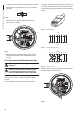
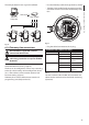
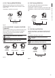
6.1.16 Serial line terminations and
connections
To set the serial line terminations operate on DIP
2.
The diagram shows two dip-switches that are used to
congure termination of the serial line.
Every peripheral that is situated at the end of a line
must be terminated using the appropriate dip-switch
in order to prevent signal reection and distortion.
Dip-switches 7 and 8 terminate serial lines RS485-1
and RS485-2 respectively.
SERIAL LINE TERMINATIONS DIP 2 AND
CONNECTIONS
Description
SW 1-2-3-4-5-6
SW 7
SW 8
Conguration
Serial line
terminations
ON RS485-2 termination
enabled
OFF
RS485-2 termination
disabled
ON RS485-1 termination
enabled
OFF
RS485-1 termination
disabled
Tab. 7
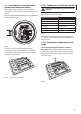
6.1.17 Setting the protocol
To set the protocol operate on DIP 1.
1
2
3
4
5
6
7
8
9
0
1
2
3
4
5
6
7
8
9
0
1
2
3
4
5
6
7
8
9
0
0
A
O
N
1
2
3
4 5
6
7
8
U
2
U
1
U
3
D
I
P
3
D
I
P
5
D
I
P
4
1
2
3
4
DIP 1
Fig. 42
Video positioning systems of the P&T can be
controlled by a range of protocols.
SETTING THE PROTOCOL DIP 1
SW 1 SW 2 SW 3 SW 4 Protocol
ON OFF ON OFF PANASONIC
OFF OFF ON OFF ERNITEC
OFF ON OFF OFF SENSORMATIC
ON OFF OFF OFF PELCO D
OFF OFF OFF OFF MACRO (VIDEOTEC)
Tab. 8
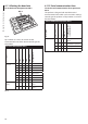
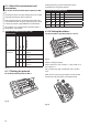
6.1.18 Setting the address
To set the address operate on DIP 3, 4 and 5.
1
2
3
4
5
6
7
8
9
0
1
2
3
4
5
6
7
8
9
0
1
2
3
4
5
6
7
8
9
0
0
A
O
N
1
2
3
4 5
6
7
8
U
2
U
1
U
3
D
I
P
3
D
I
P
5
D
I
P
4
1
2
3
4
Fig. 43
Address setting example:
Units number 431, dip-switch 3 = 4, dip-switch 4 = 3,
dip-switch 5 = 1.
Dip 3 set the cent, Dip 4 set the dec, Dip 5 set the
unit.
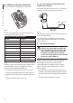
After you have set your parameters re-connect the
board on the J4 plug of the connection board.
Fig. 44