
Instruction Manual

Instructions manual - English - EN
25
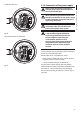
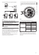
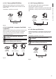
6.1.11 Unit address, communication
protocol and baud rate setting
Before powering the device it must be correctly
congured by setting the dip switches on the circuit
board.
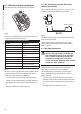
Take the conguration board from its J4 connector on
the connector board.
F
U
S
E
F
U
S
E
100nMBW3
L
N
VAR3
VAR1
AC
AL1
AL2
AL3
AL4
AL5
COM
RL1
RL1
RL2
RL2
GND
W
GND
B
A
B
A
IN
J1
J6
J2
J3
J8
J7
FUS1
VAR2
VIDEO - 1
VIDEO - 2
RS485
FUS2
J9
J4
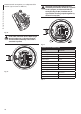
Fig. 34
This board is used to set the communication
parameters of the serial lines RS485-1 and RS485-
2: the address of the receiver, the communication
protocol and baud rate.
1
2
3
4
5
6
7
8
9
0
1
2
3
4
5
6
7
8
9
0
1
2
3
4
5
6
7
8
9
0
0
A
O
N
1
2
3
4 5
6
7
8
U
2
U
1
U
3
D
I
P
3
D
I
P
5
D
I
P
4
1
2
3
4
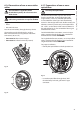
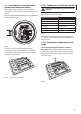
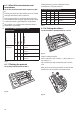
Fig. 35 Address and protocol board.
6.1.12 Conguration of the dip-switches
Operating mode valid only on version with
IP board.
The unit can be congured in one way only. Set the
DIP exactly as shown in the table.
IP BOARD CONFIGURATION
Address 1
Protocol MACRO
Baudrate 38400
Serial line One-way RS485
Termination of serial line 1 ON
Termination of serial line 2 ON
Tab. 4
Once the dip-switches have been congured, close
the door and start conguring the IP parameters of
the pan & tilt.
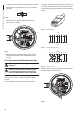
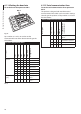
6.1.13 Setting the conguration check
mode
To set the operating mode operate on DIP 2.
SW 1=ON: Display Conguration. To be used only
to verify the conguration at the end of the setting.
During normal operation make sure the lever is on
OFF (SW 1=OFF).
1
2
3
4
5
6
7
8
9
0
1
2
3
4
5
6
7
8
9
0
1
2
3
4
5
6
7
8
9
0
0
A
O
N
1
2
3
4 5
6
7
8
U
2
U
1
U
3
D
I
P
3
D
I
P
5
D
I
P
4
1
2
3
4
DIP 2
Fig. 36