
Instruction Manual

EN - English - Instructions manual
24
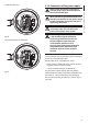
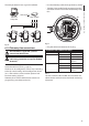
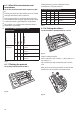
6.1.10 Alarm and relay connections
The alarm contacts are present on J3 connector.
J3
Fig. 32
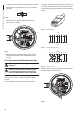
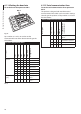
The unit is provided with 5 clean contact alarms and
2 output relays with clean contact.
CONNECTING THE ALARMS AND RELAY
Terminal Description
RL2 Relay 2 Terminal A
RL2 Relay 2 Terminal B
RL1 Relay 1 Terminal A
RL1 Relay 1 Terminal B
COM A1-A2-A3-A4-A5 alarms
ground
AL5 Alarm 5 (clean contact)
AL4 Alarm 4 (clean contact)
AL3 Alarm 3 (clean contact)
AL2 Alarm 2 (clean contact)
AL1 Alarm 1 (clean contact)
Tab. 3
All alarms have an approximate reach of 200m, which
can be obtained using an unshielded cable with a
minimum section of 0.25mm² (AWG 30).
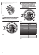
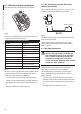
• Pass the alarms cables through the entry device.
• Take the J3 removable female connector from the
connectors board and connect the alarm wires to
it.
• Plug the cabled connector to J3 plug.
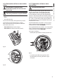
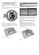
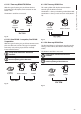
6.1.10.1 Connecting an alarm with clean
contact (dry contact)
For a clean contact alarm (alarms AL1, AL2, AL3, AL4
and AL5), carry out the following connection:
A1 G
Clean contact
Fig. 33
The clean contact alarm can be NO (normally open)
or NC (normally closed).
For further details on conguring and using the
alarms, refer to the related chapter (9.6.6.1 Alarms
Menu, page49).
6.1.10.2 Relay connection
Relays can be used for low working
voltages only (up to 30Vac or 60Vdc) and
with a maximum current of 1A. Use cables
with a section suitable for the load to be
controlled. Use cables with a minimum
section of 0.25mm² (AWG 30) and maximum
section of 1.5mm² (AWG 16).
Relays do not have polarity and therefore both
terminals of the same relay can be swapped for
alternating or continuous current voltages.
For further details on conguring and using the
relays, check the relative chapter (9.6.6.1 Alarms
Menu, page49).
• Pass the relays cables through the entry device.
• Take the J3 removable female connector from the
connectors board and connect the relays wires to
it.
• Plug the cabled connector to J3 plug.