
Instruction Manual

Instructions manual - English - EN
23
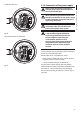
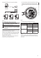
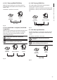
The example below shows a typical installation.
Hub / SwitchPersonal
Computer
UTP cat 5E
UTP cat 5E
Fig. 30
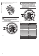
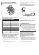
6.1.9 Telemetry line connections
The installation is type TNV-1, do not
connect it to SELV circuits.
In order to reduce the risk of re, only use
cable sizes greater than or equal to 26AWG
(0.35mm²)
The J9 connector supplies 2 RS485 serial
communication lines (Tab. 2, page23).
The lines can be congured in various ways according
to the dip-switch settings of the conguration board
(6.1.11 Unit address, communication protocol and
baud rate setting, page25).
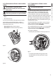
Telemetry lines connect the device to control and
programming units (keyboard or PC).
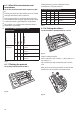
• Pass the telemetry cables through the entry device.
• Take the J9 removable female connector from the
connectors board and connect the telemetry wires
to it.
F
U
S
E
F
U
S
E
100nMBW3
L
N
VAR3
VAR1
AC
AL1
AL2
AL3
AL4
AL5
COM
RL1
RL1
RL2
RL2
GND
W
GND
B
A
B
A
IN
J1
J6
J2
J3
J8
J7
FUS1
VAR2
VIDEO - 1
VIDEO - 2
RS485
FUS2
J9
J9
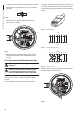
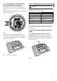
Fig. 31
• Plug the cabled connector to the J9 plug.
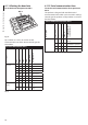
TELEMETRY LINES CONNECTION TABLE
Serial line Terminal Description
RS485-1 A (+) RS485 line (1)
B (-) RS485 line (1)
SGND RS485-1 line
reference
RS485-2 A (+) RS485 line (2)
B (-) RS485 line (2)
SGND RS485-2 line
reference
Tab. 2
The last 2 contacts (W and GND) of J9 connector are
referred to the external washer tank level monitoring
(if present).