
Instruction Manual

Instructions manual - English - EN
21
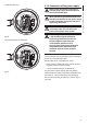
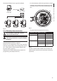
6.1.6 Connections of one or more video
cables
The installation is type CDS (Cable
Distribution System), do not connect it to
SELV circuits.
In order to reduce the risk of re, only use
cable sizes greater than or equal to 26AWG.
Suggested coaxial cables are:
• RG59
• RG174A/U UL1354
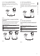
Pass the coaxial cable(s) through the entry device.
Connect the coaxial cable through a 75 Ohm
BNC male connector (not supplied) to video BNC
connector(s) J6 (and J7).
• Connector J6: Main camera output.
• Connector J7: Infrared camera (if present).
Fig. 21
Fig. 22
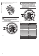
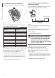
6.1.7 Connections of one or more
optical ber
Use adequate optical ber.
The transmission of video signal or data can be
done by optical ber. In the conguration with
single camera, in the only available optical ber,
is transmitted the video signal and the telemetry
control. In the conguration with double camera, the
telemetry control is present only in the optical ber
No. 1 (No. 1 on the video, visible camera) whereas in
the optical ber No.2 is transmitted the video signal
of the thermal camera.
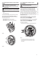
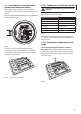
For Multi Mode ber transmitters, use 62.5/125µm
with a maximum length of 3km. Use a receiver for
Multi Mode ber model: FORXMM01
For Single Mode ber transmitters, use 9/125µm ber
with a maximum length of 69km. Use a receiver for
Single Mode ber model: FORXSM01
For proper installation:
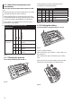
• Identify the optical ber inside the junction box.
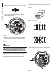
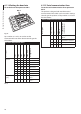
100nMBW3
L
N
VAR3
VAR1
AC
AL1
AL2
AL3
AL4
AL5
COM
RL1
RL1
RL2
RL2
GND
W
GND
B
A
B
A
IN
J1
J6
J2
J3
J8
J7
FUS1
VAR2
VIDEO - 1
VIDEO - 2
RS485
FUS2
J9
Fig. 23
• Insert the optical ber through the ¾” NPT
threaded entry hole and graft with ST type
connector.