
Instruction Manual

EN - English - Instructions manual
20
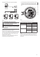
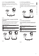
Protective earth connections, use adequate cable
sections (up to 2.5mm² or AWG 14)
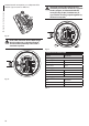
J1
Fig. 18
Earth cable should be about 10mm longer
than the other two, so that it will not be
disconnected accidentally if the cable is
stretched or pulled.
F
U
S
E
F
U
S
E
100nMBW3
L
N
VAR3
VAR1
AC
AL1
AL2
AL3
AL4
AL5
COM
RL1
RL1
RL2
RL2
GND
W
GND
B
A
B
A
IN
J1
J6
J2
J3
J8
J4
J7
FUS1
VAR2
VIDEO - 1
VIDEO - 2
RS485
ADDRESS & PROTOCOL
FUS2
J9
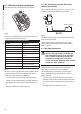
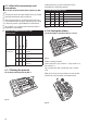
Fig. 19
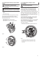
The power supply cable should also be
covered by the silicone sheath (01) supplied
for this purpose, and fastened with the
corresponding tie (02). Furthermore, all
signal cables must be grouped together by
means of a strap (03).
F
U
S
E
F
U
S
E
100nMBW3
L
N
VAR3
VAR1
AC
AL1
AL2
AL3
AL4
AL5
COM
RL1
RL1
RL2
RL2
GND
W
GND
B
A
B
A
IN
J1
J6
J2
J3
J8
J4
J7
FUS1
VAR2
VIDEO - 1
VIDEO - 2
RS485
ADDRESS & PROTOCOL
FUS2
J9
02
01
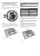
Fig. 20
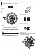
POWER SUPPLY CONNECTION
Colour Terminals
Power supply 24Vac
Dened by the installer (N) Neutral
Dened by the installer (L) Phase
Yellow/Green Earth
Power supply 230Vac
Blue (N) Neutral
Brown (L) Phase
Yellow/Green Earth
Power supply 120Vac
Blue (N) Neutral
Brown (L) Phase
Yellow/Green Earth
Tab. 1