
Instruction Manual

Instructions manual - English - EN
19
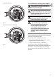
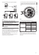
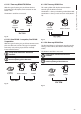
Cable the wires on it.
F
U
S
E
F
U
S
E
100nMBW3
L
N
VAR3
VAR1
AC
AL1
AL2
AL3
AL4
AL5
COM
RL1
RL1
RL2
RL2
GND
W
GND
B
A
B
A
IN
J1
J6
J2
J3
J8
J4
J7
FUS1
VAR2
VIDEO - 1
VIDEO - 2
RS485
ADDRESS & PROTOCOL
FUS2
J9
Fig. 16
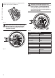
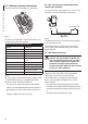
Plug the connector on the board.
F
U
S
E
F
U
S
E
100nMBW3
L
N
VAR3
VAR1
AC
AL1
AL2
AL3
AL4
AL5
COM
RL1
RL1
RL2
RL2
GND
W
GND
B
A
B
A
IN
J1
J9
J6
J2
J3
J8
J4
J7
FUS1
VAR2
VIDEO - 1
VIDEO - 2
RS485
ADDRESS & PROTOCOL
FUS2
Fig. 17
6.1.5 Connection of the power supply
Always make the electrical connections
with the power supply disconnected and
the circuit-breaker open.
When commencing installation make sure
that the specications for the power supply
for the installation correspond with those
required by the device.
Make sure that the power source and
connecting cables are suitable for the
power consumption of the system.
The building must be equipped with
a 15A maximum bipolar protection
circuit (magnetothermal), that must
include a bipolar automatic-type
circuit breaker, which must also
envisage earth fault current protection
(magnetothermal+dierential) with
minimum distance of 3mm between
contacts.
The device is available in versions for dierent power
supply voltages: the value for the particular device is
shown on its identication label.
Power cables to be used: AWG16 (1,5mm²).
• Earth wire type TEWN with cross section equal or
bigger than line and neutral cable.
• Line and neutral wire type TFFN or MTW
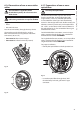
Pass the power cables through the entry device.
Take from the connectors board the removable male
connector J1. Connect the power wires following
the connector labeling for polarity as shown (Fig. 18,
page20).